Dual role antenna assembly

a dual-role, antenna technology, applied in the direction of simultaneous aerial operations, electrical equipment, structural forms of the radiation element, etc., can solve the problems of never completely uniform radiation pattern and higher gain in one direction, and achieve the effect of sufficient omnidirectionality and enhanced low elevation angle gain

Active Publication Date: 2020-04-07
SKYWAVE MOBILE COMM
View PDF59 Cites 2 Cited by
  • Summary
  • Abstract
  • Description
  • Claims
  • Application Information

AI Technical Summary

Benefits of technology

[0009]Embodiments of the invention employ a diversity antenna system that uses a tilted radiation pattern to enhance low elevation angle gain for one higher priority satellite, while maintaining sufficient omnidirectionality to function well with the remaining satellites.
[0011]It will be understood that substantially omnidirectional in this context means that the antenna generally has all round coverage to receive (or transmit) signals from any direction outside of a small exclusion zone where reception (or transmission) is impaired. However, a radiation pattern is never completely uniform and in practice one direction has higher gain. Also, the gain pattern is generally tilted relative to the horizon, so that one sector will have better low elevation performance.
[0015]The bandwidth limitations of the CIFA element can be partly overcome by increasing the height the antenna, for example, by doubling the height to 12 mm. Thus, the height of the curled inverted-F antenna should be at least 12 mm for good bandwidth performance in GEO systems with typical manufacturing tolerances. However, in addition, multiple feed strips can be provided for the antenna to optimize its performance for multiple sub-bands. An RF switching module is provided in this case to switch between the feed strips according to the required sub-band depending on the particular frequency in use.
[0017]Unlike MBAs in the prior art, where the object is usually to create a directional beam, in accordance with the present invention the object of the MBA is to achieve omnidirectional coverage. The composite radiation pattern is achieved by connecting the RF front-end directly to the array element corresponding with the desired beam pattern. The superposition of individual element radiation patterns creates and an aggregate MBA radiation pattern. Keeping only one element active at a time is necessary to ensure that the MBA effective aperture area remains small, facilitating a more omnidirectional radiation pattern.
[0019]To facilitate the design of the underlying antenna element, it is preferable to have the systems involved operate in nearby frequency bands. This enables simultaneous GEO / GNSS operation with the same RF front-end.

Problems solved by technology

However, a radiation pattern is never completely uniform and in practice one direction has higher gain.

Method used


Image

  • Dual role antenna assembly
  • Dual role antenna assembly
  • Dual role antenna assembly

Examples


Embodiment Construction

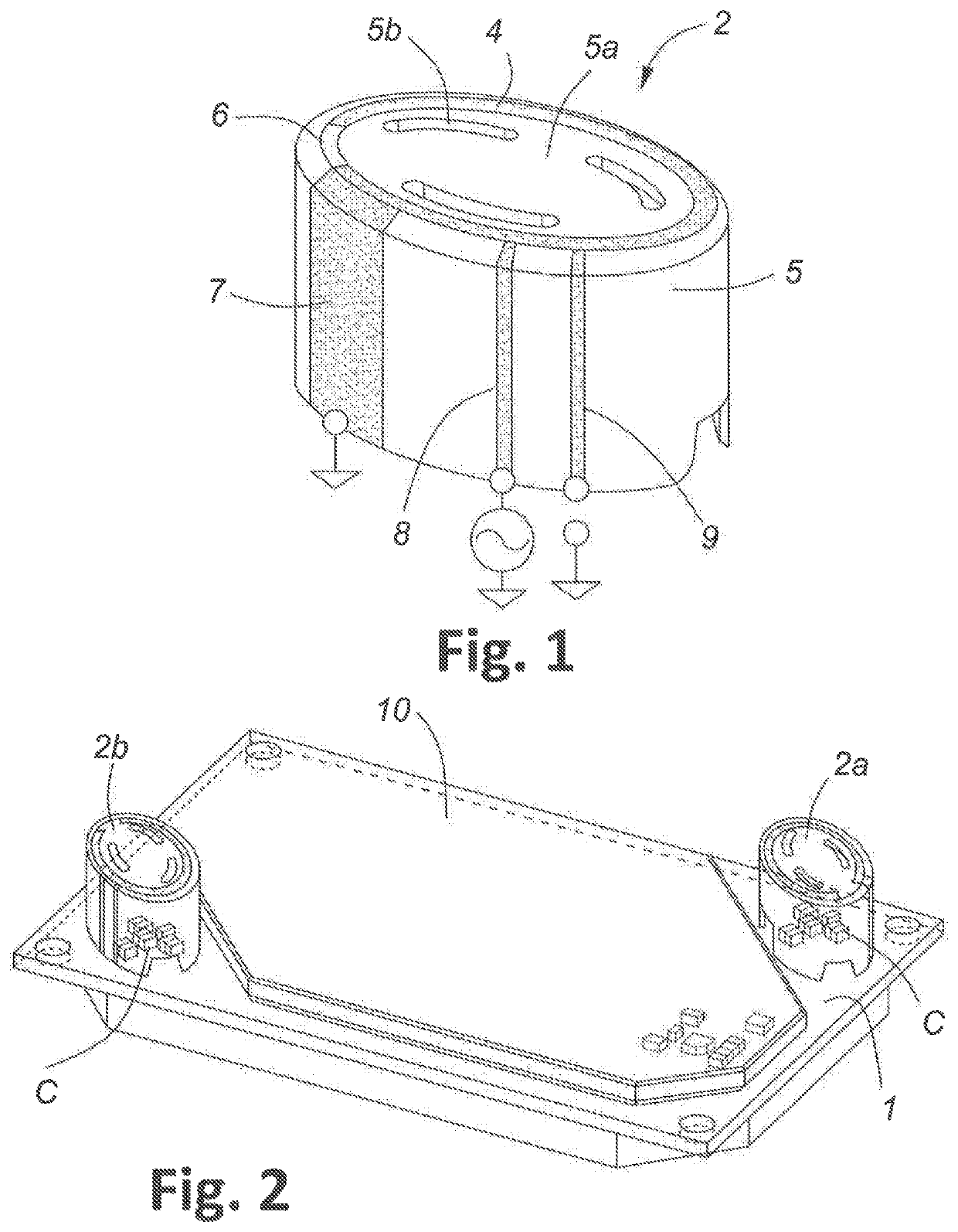
[0033]The antenna element 2 shown in FIG. 1 is a curled inverted-F antenna comprising an interrupted curled metal strip 4 mounted or plated on the end of a hollow elliptical cylindrical dielectric form 5 with a closed top 5a having arcuate slits 5b.

[0034]While an elliptical shape illustrated has been found to give good performance, it will be understood that other shapes, such as circular cylindrical, may be employed. The elliptical shape has the added benefit of allowing a more space efficient use of the top side of a printed circuit board.

[0035]A small gap 6 is present between the ends of the interrupted circular metal strip 4. One ground strip 7 and two metal feed strips 8, 9, extend vertically from one end of the metal strip 4. Ground strip 7 is connected to the ground plane provided by the printed circuit board (PCB) 1. The other feed strips 8, 9 correspond to different frequency sub-bands.

[0036]A two-element antenna assembly shown in FIG. 2 comprises a generally rectangular d...


PUM


Abstract

A dual role antenna assembly operable for use with GEO and LEO / MEO satellites has at least two curled inverted-F substantially omnidirectional antennas mounted on a ground plane. The antennas have asymmetrical gain patterns favoring certain sectors and are oriented such that the favored sectors of the different antenna face different directions. A controller selects the antenna for connection to an RF front-end in accordance with predetermined performance criteria.

Description

FIELD OF THE INVENTION[0001]This invention relates to the field of antenna, and more particularly to a dual role antenna assembly operable for use with use with geostationary earth orbit (GEO) and low earth orbit / medium earth orbit (LEO / MEO) satellite constellations, and to a method of controlling such an antenna.BACKGROUND OF THE INVENTION[0002]Designers of mobile satellite communication antenna systems are faced with a number of conflicting system requirements. The link budget benefits from higher gain, but an omnidirectional pattern is best from a system coverage perspective. The antennas should be low profile and yet have good low elevation angle performance. They should also be small and yet have sufficiently wide bandwidth.[0003]Exploring these trade-offs typically leads to the selection of patch antenna technology if maintaining a low profile is critical, or helical antennas if profile is less important but low elevation angle performance is vital. Furthermore, maintaining lo...

Claims


Application Information

Patent Timeline
Patent Type & Authority Patents(United States)
IPC IPC(8): H01Q5/50H01Q3/24H01Q1/38H01Q9/04
CPCH01Q3/24H01Q5/50H01Q1/38H01Q9/0442H01Q9/0428H01Q9/0421
Inventor LAFLEUR, PHILROSCOE, DAVID
Owner SKYWAVE MOBILE COMM
Why Eureka
Try Eureka