Key and corresponding lock

a technology for cylinder locks and keys, applied in cylinder locks, building locks, construction, etc., can solve the problems of illegal keys easily being brought into circulation, control points on both sides of keys must be identical, and the effect of hard copy

Active Publication Date: 2020-04-14
EVVA SICHERHEITSTECHNOLOGIE GMBH
View PDF26 Cites 0 Cited by
  • Summary
  • Abstract
  • Description
  • Claims
  • Application Information

AI Technical Summary

Benefits of technology

[0007]It is an object of the invention to overcome these and further problems of conventional keys and locks. In particular, a new key and a new lock shall be realized which offer sufficient possible combinations and are hard to copy. In particular, the invention is meant to solve the problem that presents the ease with which reversible keys can be copied. It is furthermore intended to provide a possibility to lock a plurality of different reversible key locking systems using the same key.

Problems solved by technology

When rotated about its longitudinal axis, a reversible key in each case has the same features thereof and can, therefore, —independently of the side of the key which is pointing upwards—also be introduced into the keyway of the associated lock cylinder in a rotated fashion, which is not possible in the case of a normal key with notches on one side.
This is disadvantageous with regard to modern reproduction methods (high-resolution smartphone cameras in combination with 3D printing), as illegal keys can easily be brought into circulation.
Furthermore, in the case of reversible keys with laterally arranged control points, the problem emerges that the control points on both sides of the key must be identical in the sense of the above definition.
However, limitations for the realization of the control points at the key tip result: The central position of the tumbler at the key tip cannot be used, as there would otherwise be an increased danger of breakage.

Method used


Image

  • Key and corresponding lock
  • Key and corresponding lock
  • Key and corresponding lock

Examples


Embodiment Construction

[0054]The invention is explained in more detail in the following on the basis of non-limiting exemplary embodiments:

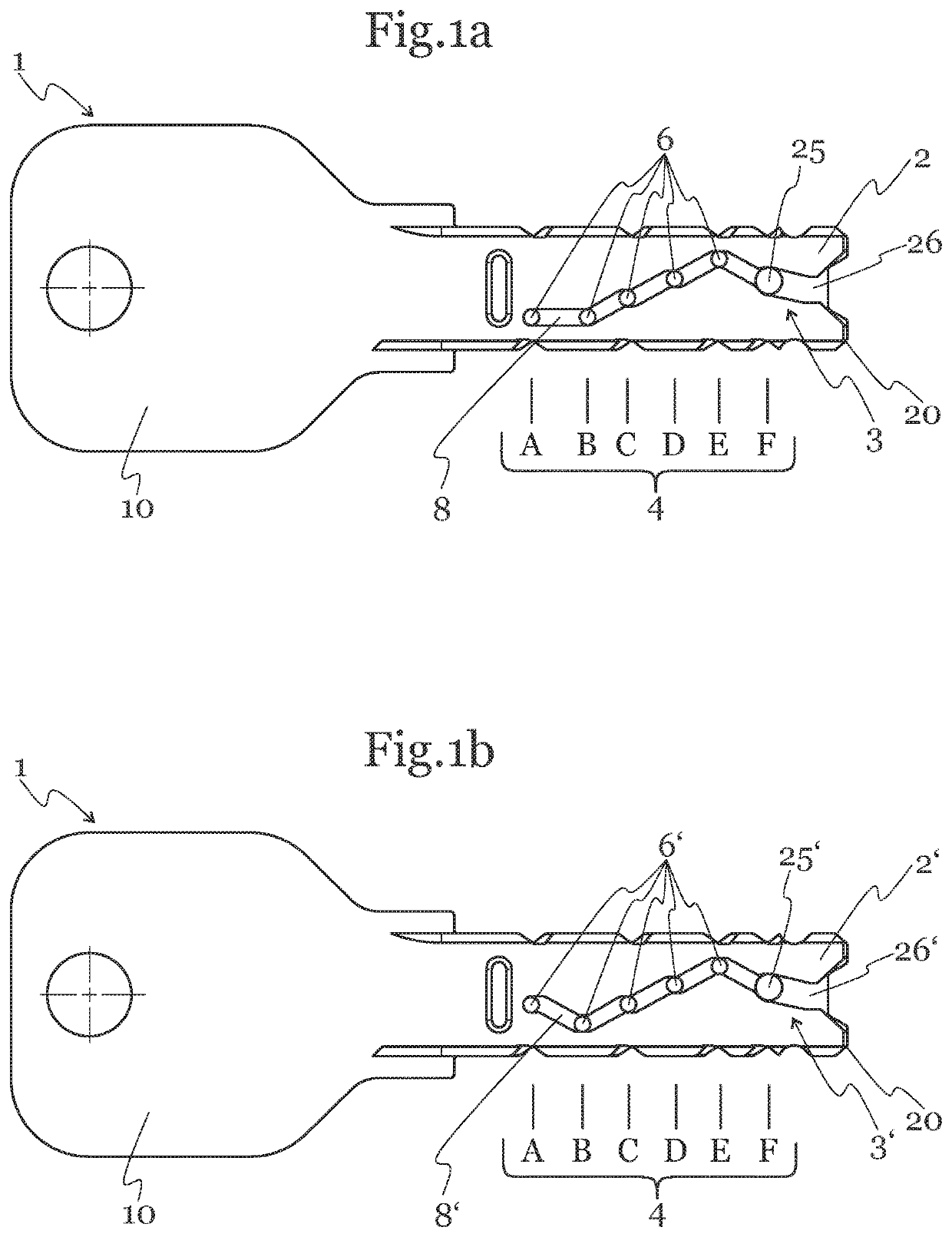
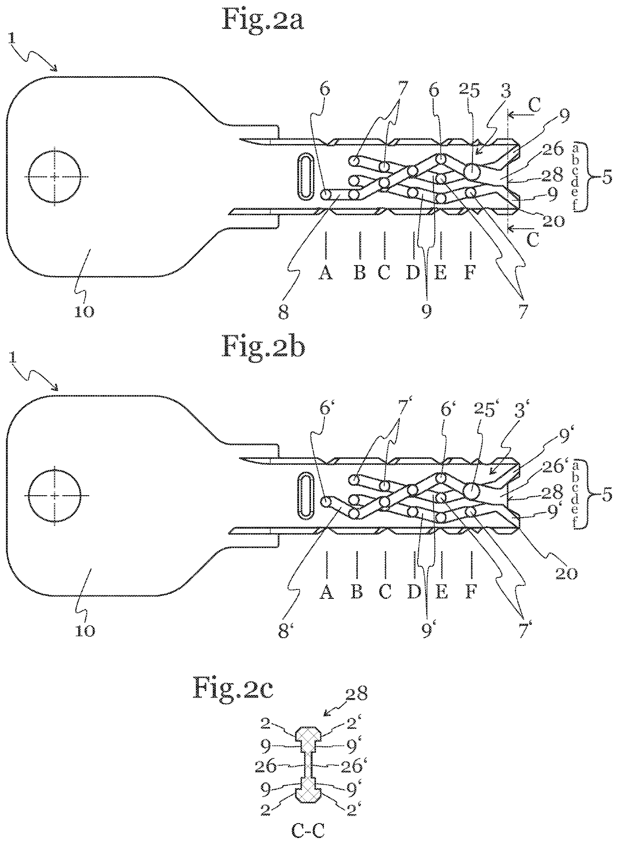
[0055]FIGS. 1a-1b show an exemplary embodiment of a key 1 according to the invention, which is realized as a flat key with a key bow 10 and a key tip 20 and two opposite surfaces 2, 2′. FIG. 1a shows a view of the first surface 2, FIG. 1b shows a view of the second surface 2′. The surfaces 2, 2′ are the key flat sides.

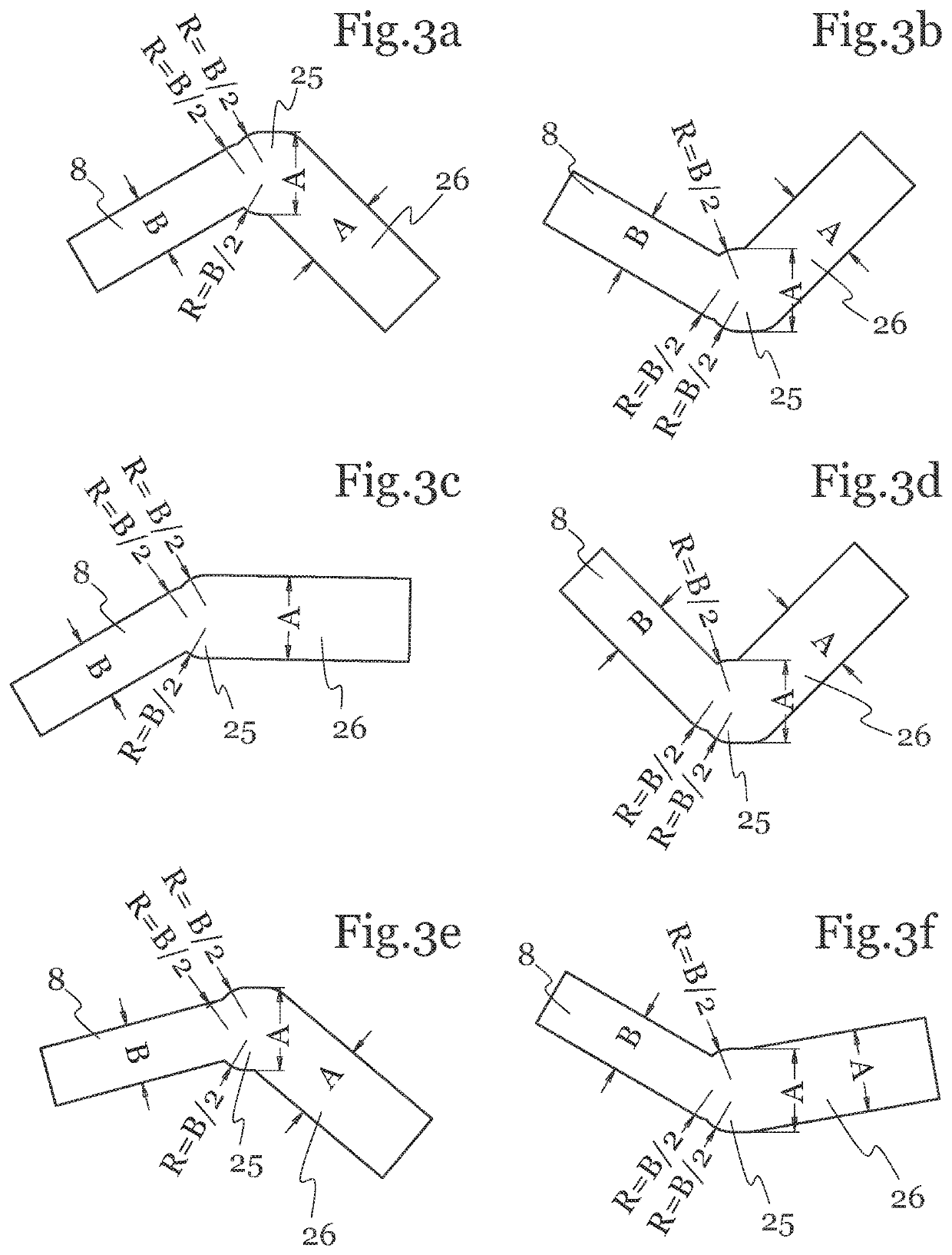
[0056]Sensing positions 4, namely six sensing positions A-F, are provided for both surfaces 2, 2′ along the longitudinal extent of the key 1. A code 3, 3′ is located at each sensing position 4 on both surfaces 2, 2′ of the key 1, wherein the first code 3 is provided on the surface 2 and the second code 3′ is provided on the surface 2′. The codes 3, 3′ comprise control points 6, 6′ which are arranged at certain control heights and are connected to one another by means of control grooves 8, 8′.

[0057]The control points are realized differently on the sensing...


PUM


Abstract

The invention relates to a key (1) for locking a cylinder lock, comprising at least one first surface (2) and at least one second surface (2′), with sensing positions (4) provided along the longitudinal extent of the key (1), wherein at least one code (3) is provided on the first surface (2) and wherein at least one further code (3′) is provided on the second surface (2′), the codes comprising control points (6, 6′, 7, 7′) at the sensing positions (4) that are provided transversely to the longitudinal extent of the key (1) and arranged at certain control heights (5), wherein at least at one sensing position (4) at least one control point (25, 25′) has a different dimension, preferably a larger diameter, on the two surfaces than a control point (6, 6′, 7, 7′) at another sensing position (4). The invention also relates to a lock for such a key and a system made up of at least two locks and at least one key.

Description

RELATED APPLICATIONS[0001]This application is a National Phase of PCT Patent Application No. PCT / EP2017 / 055628 having International filing date of Mar. 10, 2017, which claims the benefit of priority of Austrian Patent Application No. A50203 / 2016 filed on Mar. 11, 2016. The contents of the above applications are all incorporated by reference as if fully set forth herein in their entirety.FIELD AND BACKGROUND OF THE INVENTION[0002]The invention relates to a key for locking a cylinder lock, having at least one first surface and at least one second surface and sensing positions provided along the longitudinal extent of the key, wherein at least one code is provided on the first surface and wherein at least one further code is provided on the second surface, the codes comprising control points at the sensing positions that are provided transversely to the longitudinal extent of the key and arranged at certain control heights. The invention also relates to a cylinder lock for a key of thi...

Claims


Application Information

Patent Timeline
Patent Type & Authority Patents(United States)
IPC IPC(8): E05B27/00E05B19/00E05B27/10
CPCE05B27/0017E05B27/0042E05B19/0064E05B27/0082E05B27/0078E05B2027/10E05B19/0017E05B19/0052E05B27/00E05B29/00E05B19/0035E05B19/04E05B27/086E05B29/0066E05B27/10
Inventor BAUMHAUER, WALTER
Owner EVVA SICHERHEITSTECHNOLOGIE GMBH
Why Eureka
Try Eureka