Foam soap dispenser

a soap dispenser and foam technology, applied in the field of foam soap dispensers, can solve the problems of affecting the quality of soap, and affecting the use of soap, so as to reduce the manufacturing cost of parts, and mix more accurately

Active Publication Date: 2020-04-21
YAN JIANZHI
View PDF14 Cites 2 Cited by
  • Summary
  • Abstract
  • Description
  • Claims
  • Application Information

AI Technical Summary

Benefits of technology

[0017]In the above-mentioned technical solution, a paste-like or thick liquid soap raw material is mixed with water in the mixing device to be diluted to a proper concentration. Thereafter, the liquid soap enters the foaming device, so that the foam is produced and discharged. Accordingly, the requirement for foam production and discharge of the liquid soap raw material with high concentration can be satisfied, the restrictions of use are reduced, and it is more suitable for people to use. Additionally, both the mixing device and foaming device are actuated by one drive device, such that the space occupation of the soap dispenser is significantly reduced, making the soap dispenser more compact.
[0028]In the above-mentioned technical solution, the foaming device inlet is connected to the water chamber and the material chamber via pipes, respectively, to form a dual-path soap dispenser. With the effect of the liquid dispensing and transmitting device and the material dispensing and transmitting device, the water and the paste-like or thick liquid soap raw material can arrive at the foaming device inlet at a proportion at the same time. After materials entering the foaming device are diluted, the requirement for foam production and discharge of the paste-like or thick liquid soap raw material can be satisfied, such that the restrictions of use are reduced and it is more suitable for people to use.
[0041]In the above-mentioned technical solution, the mixing device is provided with the mixed groove to achieve the mixing of the water and the raw material at a proportion. The raw material can be well controlled, and the discharge of the liquid soap is effective. Moreover, since the mixing crown gear and the mixing straight gear are provided, the engagement of the mixing crown gear and the mixing straight gear can achieve an additional mixing of the raw material. Moreover, at a top of the mixing crown gear there is provided with the stirring pieces, so as to rub the raw material into the mixing groove easily, such that the mixing of the raw materials is more uniform. Additionally, the structure design of the whole soap dispenser is intellectual and compact, and user can simply trigger the pressing pieces of the trigger device to control the entire soap dispenser system at a time, such that a simple and efficient system without complicated process can be achieved. The drive-pumping device, the mixing device, and the foaming device can be simultaneously controlled by simply triggering the pressing pieces of the trigger device.
[0050]In the above-mentioned technical solution, the mixed liquid pumping-transmitting device and liquid pumping-transmitting device are designed separately, such that the water and the raw material can be mixed more accurately at a proportion to effectively produce foam. The drive device is properly designed as a gear assembly, such that multiple modules of the provided system can be actuated simultaneously, and the operation thereof is easy, time-saving and labor-saving, effective, and can reduce the manufacturing cost of the parts. Moreover, the mixing device of the foam soap dispenser adopts a intellectual structure design where the liquids can be mixed first and stirred subsequently. The rotation of the mixing gear mixes the liquid soap at first and the stirring gear carries out a fine stirring to completely mixture of the water and the raw material, such that the mixed liquid can be more uniform, and a good foundation for an effective foaming may be established.
[0051]In view of above, the present invention can produce plentiful foam, and the piston assembly thereof is not easy to be stuck, and is provided with a longer service life. Moreover, the produced foam has a uniform size while the discharge speed of foam is faster and more stable than ever.

Problems solved by technology

If these products are used directly without water, no foam would be created, which make user's skin more susceptible to damage with the concentrated liquid soap.
In addition, foaming the liquid soap by hand is prone to cause a great waste and be harmful to the environment because a large amount of liquid soap may be used than necessary.
However, the out-of-date soap dispenser which simply outputs liquid soap cannot satisfy the pursuit of comfortable life style of contemporary people anymore.
However, by doing so only a few of foam can be generated and the piston assembly is struggling with being stuck and short of service life.
In this case, the arrangement of the grid-like or mesh-like barrier would be necessary, and the arrangement of the grid-like or mesh-like barrier turns out to be a trouble slowing down the speed of the discharging liquid because the liquid soap is blocked.
The screw-type liquid-pumping device has a problem of backflow which slows down the speed of second liquid pumping, resulting in an unstable foam volume.
Additionally, the assembly is struggling with being stuck, short of service life and easy of leakage.

Method used


Image

  • Foam soap dispenser
  • Foam soap dispenser
  • Foam soap dispenser

Examples


embodiment 1

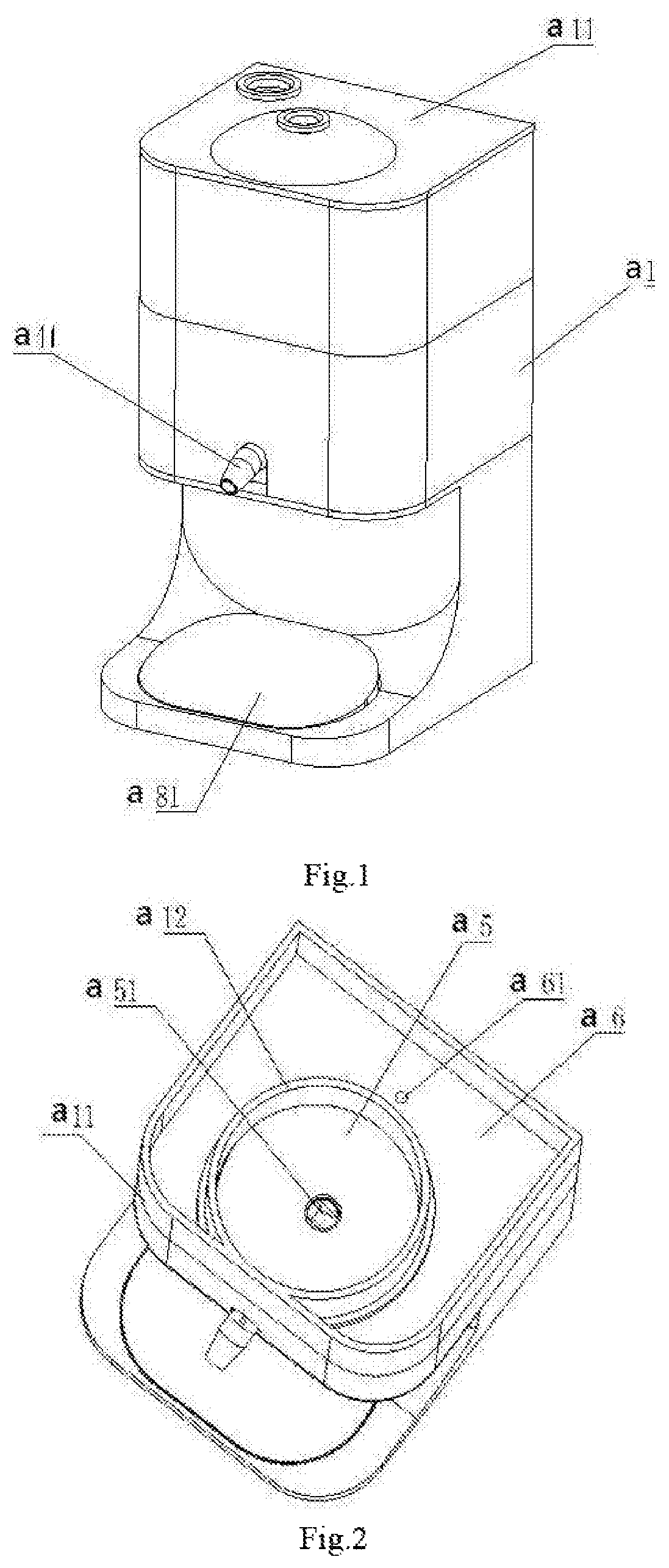
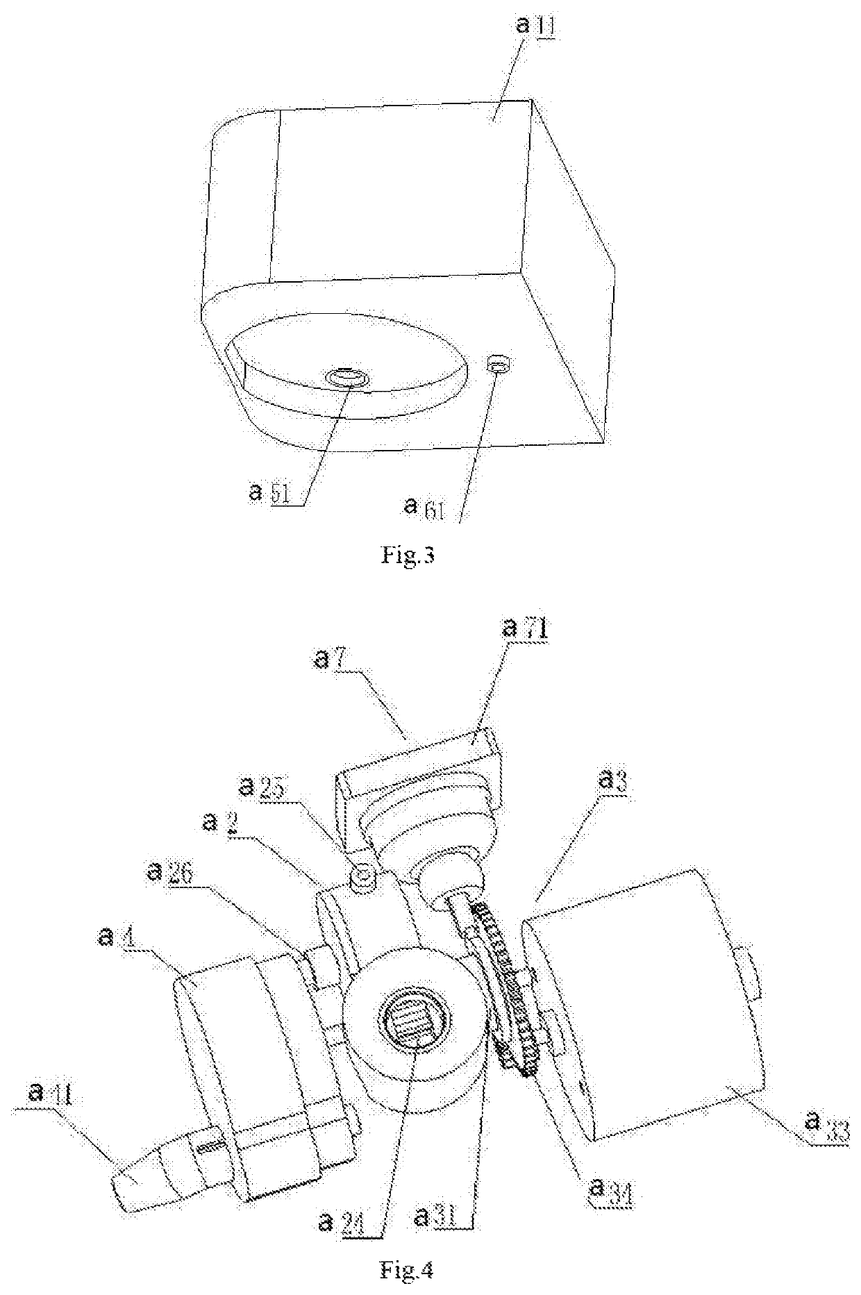
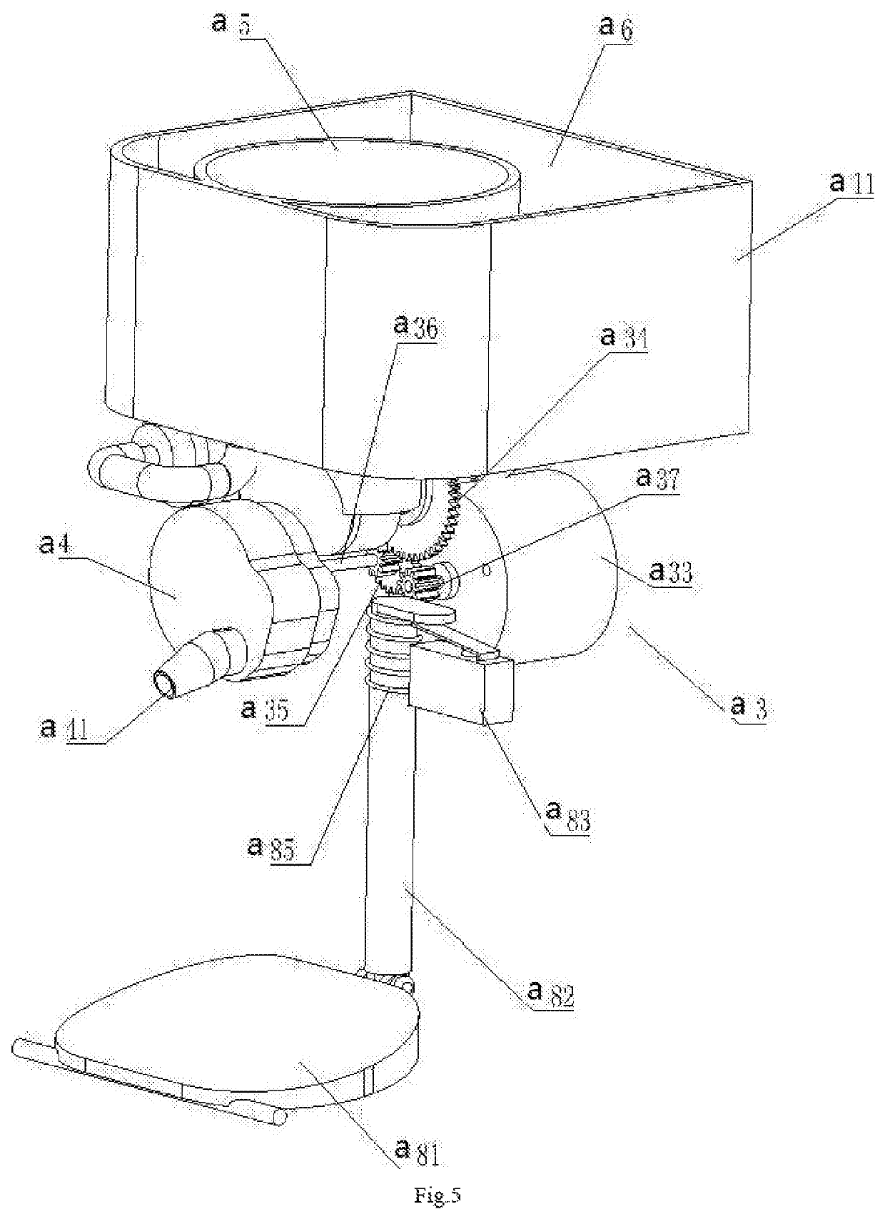
[0097]A multi-functional foam soap dispenser, with reference to FIGS. 1-8, includes a housing a1 provided with a liquid soap outlet. The housing a1 is internally provided with a mixing device a2, a foaming device a4, a drive device a3, a raw material chamber a5, and a water chamber a6. Wherein, the mixing device a2 is provided with a feed port a24, a water inlet a25, and a discharge port a26. The feed port a24 is connected to a discharge port a51 of the raw material chamber a5 via a pipe. The water inlet a25 is connected to a water outlet a61 of the water chamber a6 via a pipe. The discharge port a26 of the mixing device a2 is connected to an inlet of the foaming device a4 via a pipe. The liquid soap outlet is connected to an outlet of the foaming device a4. Raw materials in the raw material chamber a5 and water in water chamber a6 may enter the mixing device a2 at the same time and be mixed and diluted, and then enter the foaming device a4 to produce foam. At last, the foam is disc...

embodiment 2

[0117]Referring to FIGS. 13 to 15, a dual-path foam soap dispenser is provided, including a housing b1 having a liquid soap outlet. The housing b1 is internally provided with a foaming device b2, a drive device b3, a raw material chamber b4, and a water chamber b5. Moreover, the water chamber b5 is provided with a water outlet b51. The raw material chamber b4 is provided with a discharge port b41. The foaming device b2 is provided with an inlet. The inlet of the foaming device b2 is connected to the water outlet b51 of the water chamber b5 through a pipe which is provided with the liquid dispensing and transmitting device b6. The inlet of the foaming device b2 is connected to the discharge port b41 of the raw material chamber through a pipe which is provided with the raw material dispensing and transmitting device b7. The raw material dispensing and transmitting device b6 has two functions, one of which is to draw in the raw material from the raw material chamber b4 to the foaming d...

embodiment 3

[0141]As shown in FIGS. 23 to 31, an efficient multi-functional foam soap dispenser includes a housing c1 provided with a liquid soap outlet. The housing c1 is internally provided with a mixing device c2, a foaming device c4, a drive-pumping device c3, a raw material chamber c5, and a water chamber c6. The mixing device c2 includes a feed port connected to a discharge port of the raw material chamber c5, a water inlet connected to a water outlet of the water chamber c6, and a discharge port connected to an inlet of the foaming device c4. The liquid soap outlet is connected to the foaming device c4. The drive-pumping device c3 is connected to the mixing device c2 and the foaming device c4, and serves as power source for the mixing device c2 and the foaming device c4, simultaneously. The mixing device c2 includes a mixing-diluting-transmitting housing c21 and a mixing vessel c24 arranged on an upper portion of the mixing-diluting-transmitting housing c21. A side of the housing body of...


PUM

PropertyMeasurementUnit
liquid inletaaaaaaaaaa
elasticaaaaaaaaaa
rotationaaaaaaaaaa

Abstract

The present invention relates to the technical field of soap dispenser, particularly to a foam soap dispenser including a housing, a raw material chamber, and a liquid soap outlet, and further includes a water chamber, a drive device, and a foaming device; the liquid soap outlet is arranged on the housing; the raw material chamber, the water chamber, the drive device, and the foaming device are arranged inside the housing; a raw material chamber outlet and a water chamber outlet are connected to a foaming device inlet; a foaming device outlet is connected to the soap liquid outlet. The present invention can produce plentiful foam, and the piston assembly thereof is not easy to be stuck, and is provided with a longer service life. Moreover, the produced foam has a uniform size while the discharge speed of foam is faster and more stable than ever.

Description

TECHNICAL FIELD[0001]The present invention relates to the technical field of soap dispenser, and more particularly to a foam soap dispenser.BACKGROUND[0002]The existing detergents and personal care products in the market, such as hand washing, cleanser essence, shampoo, shower gel, facial cleanser, toothpaste and so on, have to be mixed with water and rubbed by hand for foaming before use. If these products are used directly without water, no foam would be created, which make user's skin more susceptible to damage with the concentrated liquid soap. In addition, foaming the liquid soap by hand is prone to cause a great waste and be harmful to the environment because a large amount of liquid soap may be used than necessary.[0003]The soap dispenser is an apparatus which can be squeezed to dispense liquid soap for users to clean their hands and faces. The soap dispenser essentially includes a liquid receiving bottle or a liquid container for receiving liquid soap, and a pumping device h...

Claims


Application Information

Patent Timeline
Patent Type & Authority Patents(United States)
IPC IPC(8): A47K5/16A47K5/12A47K5/14
CPCA47K5/1217A47K5/1207A47K5/16A47K5/1208A47K5/14A47K5/12
Inventor YAN, JIANZHI
Owner YAN JIANZHI
Why Eureka
Try Eureka