Injection device for a forming and filing a container using a pressurized liquid

a technology of injection device and filling container, which is applied in the direction of transportation and packaging, other domestic articles, packaging goods types, etc., can solve the problems of increasing the frequency and cost of system maintenance, affecting the cleaning efficiency of the system, and affecting the sealing gasket, so as to reduce the space requirement of the piston body, increase the cleaning efficiency, and reduce the effect of liquid turbulen

Active Publication Date: 2020-04-21
DISCMA
View PDF4 Cites 2 Cited by
  • Summary
  • Abstract
  • Description
  • Claims
  • Application Information

AI Technical Summary

Benefits of technology

[0013]The inventors have discovered that the speed of the pressurized liquid flowing through the outlet ducts creates a dynamic effect having a dynamic impact on the reaction force exerted by the liquid on the piston head. The inventors have discovered that placing the outlet ports equally distributed around the piston head makes the various dynamic impacts at each outlet port compensated by each other. Consequently, the resultant mechanical effort imparted on the piston head by the liquid in the inner chamber is applied in a direction substantially parallel to the piston axis or substantially equal to zero. This greatly reduces the risks of wearing the sealing gasket of the piston head since the piston head is no longer urged laterally toward the piston body.
[0032]As explained above, this method allows producing containers at high rate with a piston head operated with simultaneously high liquid pressure and high flow rate without damaging the piston head.

Problems solved by technology

As such a piston device has to be operated with simultaneously high liquid pressure and high flow rate, the piston and its sealing gasket may be subjected to mechanical efforts that urge it laterally toward the piston body, with a risk, particularly after some time, of damaging the sealing gasket and experiencing localized and early wear issues, increasing the frequency and cost of maintenance of the system.
When the gasket is worn, liquid tightness between the piston head and the piston body is no longer ensured and the piston device is no longer able to fulfil its function of pressurizing the liquid and of urging the liquid toward the injection head.
Furthermore, using the piston device in such a state would lead to soiling the hydroforming station with the liquid leaking out of the piston device.

Method used


Image

  • Injection device for a forming and filing a container using a pressurized liquid
  • Injection device for a forming and filing a container using a pressurized liquid
  • Injection device for a forming and filing a container using a pressurized liquid

Examples


first embodiment

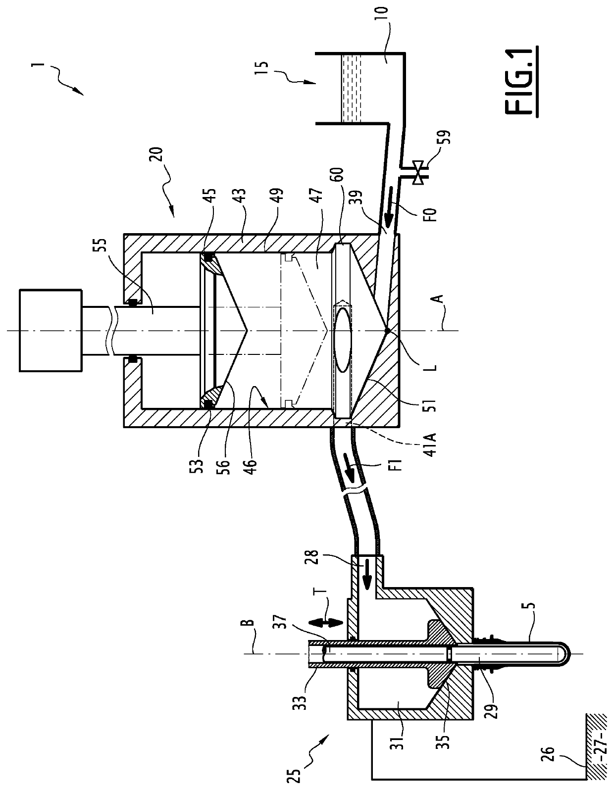
[0046]Referring to FIG. 1, there is described an injection device 1 according to the invention. The injection device 1 is included in a forming and filling station for forming a preform 5 into a container and filling the container using a liquid 10. The forming and filling station further comprises a mould cavity 6.

[0047]The injection device 1 mainly comprises a liquid source 15 for providing the liquid 10, a piston device 20 for pressurizing the liquid, and an injection head 25 for injecting the liquid into the preform 5. The injection device 1 also comprises a base 26 intended to be in horizontal contact with a floor 27.

[0048]The liquid source 15 and the injection head 25 are conventional in this type of station and will not be described in great detail herein. In particular, the injection head can move vertically.

[0049]The liquid source 15 is for example a reservoir (shown in FIG. 1).

[0050]The injection head 25, or injection nozzle, comprises an inlet 28, and an outlet 29. The in...

second embodiment

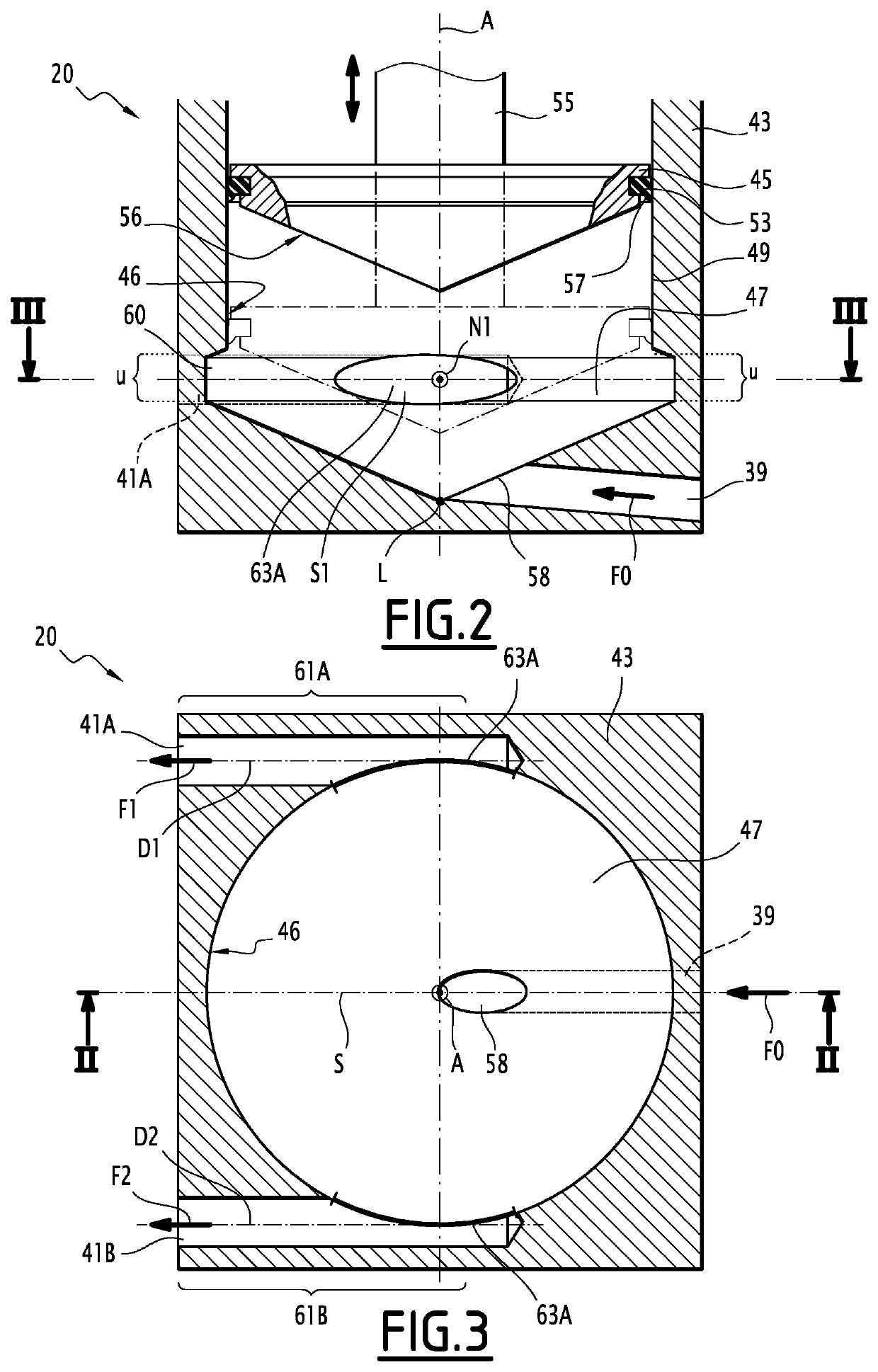
[0090]A piston device 220 according to the invention and shown in FIGS. 5 and 6 will now be described.

[0091]The piston device 220 is analogous to the piston devices 20 represented in the FIGS. 1 to 3. Similar elements have the same numeral or letter references and will not be described again. Only the differences will be described in detail here after.

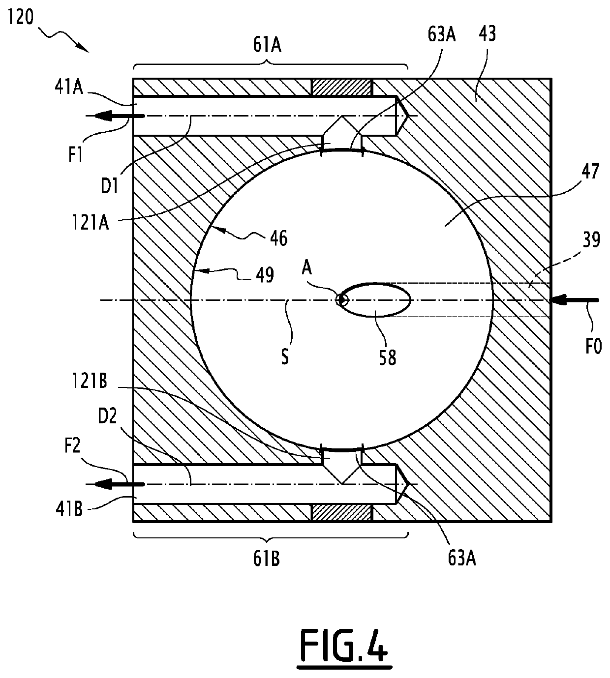
[0092]The piston device 220 differs by having ND outlet ducts 241A, 241B, 241C (FIG. 6), with ND equal to 3 in this example.

[0093]The outlet ducts 241A, 241B, 241C respectively comprise upstream portions 261A, 261B, 261C which open in the inner chamber 47 and define three outlet ports 263A, 263B, 263C in the wall 46.

[0094]The upstream portions 261A, 261B, 261C for example form angles of approximately 120° with each other. This means that the angle between two successive outlet ports and the piston axis (A) is equal to 120°. In this case, these angles are the angles formed between outlet ports 263A and 263B and the piston axis (A), betw...


PUM

PropertyMeasurementUnit
pressureaaaaaaaaaa
pressureaaaaaaaaaa
frequencyaaaaaaaaaa

Abstract

An injection device for injecting a pressurized liquid into the preform. The injection device includes a piston device having a piston body with a piston head arranged to reciprocate therein. The piston head cooperates with a sealing portion of the piston body to fluidicly isolate an inner chamber of the piston device. The piston body being in fluidic communication with a liquid source for admitting liquid into the inner chamber. The piston body including at least two outlet ducts for delivering pressurized liquid to the injection head. Each outlet duct opening defining an outlet port in a wall of the inner chamber. Each outlet port being centered on an outlet port center, wherein all the outlet port centers extend in the same radial planes of the inner chamber, are at the same distance from the piston axis and are arranged angularly in a regular manner around the piston axis.

Description

TECHNICAL FIELD OF THE INVENTION[0001]The invention generally relates to the field known as hydroforming, of forming containers from preforms using a liquid to deform the preforms and fill the obtained containers with the liquid. More specifically, the invention relates to an injection device for a forming and filling station for forming a preform into a container and filling the container using a pressurized liquid and to a method for performing the same.BACKGROUND[0002]A traditional injection device comprises a piston device including an inner chamber wherein the liquid is pressurized, and an injection head, or injection nozzle, fluidicly connected to the piston device. A connection duct communicates the pressurized liquid from an outlet port of the inner chamber toward the injection head. When the injection device is part of a hydroforming station, the injection device is designed to inject the liquid at a predetermined pressure profile and flow rate adapted to urge a preform aga...

Claims


Application Information

Patent Timeline
Patent Type & Authority Patents(United States)
IPC IPC(8): B29C49/46B65B3/02B65B3/12B29C49/42B29C49/06B29K105/00B29L31/00
CPCB65B3/022B29C49/4289B29C49/46B65B3/12B29K2105/258B29C49/06B29L2031/7158B29C2049/4664B65B3/003B29C49/42403B29C2949/0715
Inventor GILLET, DENISNASCIMBENI, MASSIMO
Owner DISCMA
Why Eureka
Try Eureka