Supercharge Your Innovation With Domain-Expert AI Agents!

Assembled floor unit

a floor unit and assembly technology, applied in flooring, construction, building construction, etc., can solve the problems of increasing production costs, large number of workers, and complicated manufacturing processes

Active Publication Date: 2020-04-21
SUPER CLICK TECH CO LTD
View PDF34 Cites 0 Cited by
  • Summary
  • Abstract
  • Description
  • Claims
  • Application Information

AI Technical Summary

Benefits of technology

The present invention provides an assembled floor unit with a bottom plate that is simple to manufacture and material-saving. The bottom plate is made by integral molding, which guarantees high production efficiency, few production process, and reduced labor cost. The middle part of the bottom plate is provided with through holes, which saves material and makes the floor easier to assemble and lay. The bottom plate meets the stability requirements for floor and is stable enough to support heavy loads. The assembled floor unit with the bottom plate is lightweight, easy to transport, and cost-effective.

Problems solved by technology

The laying and assembling of above modular floor are convenient, but the manufacturing process is slightly complicated.
However, while reducing the material costs, it also has to add extra corresponding processes, i.e. a process of manufacturing filling plates, a process of inserting the filling plate, a process of bonding a filling plate and the like, and the above-described steps require a large number of workers to complete.
Nowadays, under the circumstance of increasing labor costs, it will greatly increase production costs.
Furthermore, the existing modular floor has greater weight and is not convenient for transportation, that will increase the cost of export sales.
The bottom plate in the assembled floor unit of the prior art is limited by the traditional wooden floor, composite floor design standards and customary, and tends to adopt a frame and a filling structure to achieve sufficient mechanical strength and deformation resistance, and it is generally considered that the bottom plate of the integrated structure cannot satisfy the stability requirements for floor.

Method used


Image

  • Assembled floor unit
  • Assembled floor unit
  • Assembled floor unit

Examples


example 1

of Bottom Plate

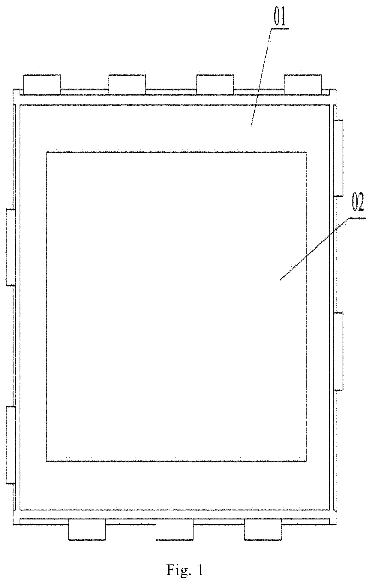
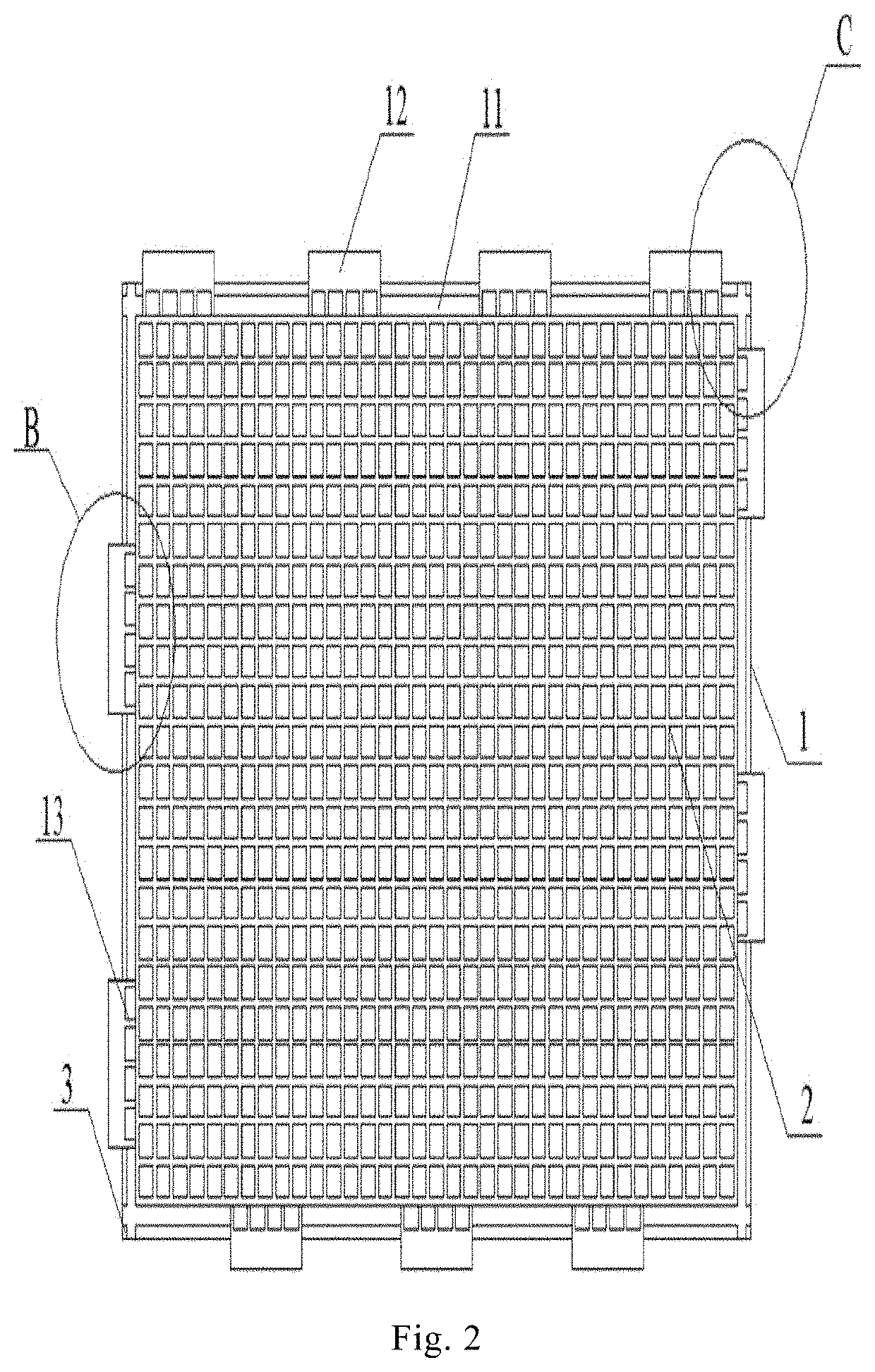
[0049]As shown in FIG. 2 and FIG. 6, a bottom plate of an assembled floor unit is preferably rectangular, and specifically may be rectangular or square. Of course, in practical applications, diamonds, octagons, hexagons, and other special shapes with curved edges are also possible. In the present embodiment, a rectangle is employed.

[0050]The bottom plate includes a frame 1 and a middle part. The bottom plate has a first surface and a second surface, the first surface being a front surface and the second surface being a back surface. At least one pair of opposite sides of the frame is provided with a clamping groove, and plurality of clamping hooks extend outwardly from at least one pair of opposite sides respectively. In this embodiment, a clamping groove 11 is formed on the back surface of the bottom plate along the side of the frame 1. The opening side 11a of the clamping groove 11 faces the back surface of the bottom plate. The clamping hook 12 extends outwardly fr...

example 2

of Bottom Plate

[0060]The configuration in this embodiment is substantially the same as the first embodiment except that the middle part of the bottom plate is different. As shown in FIG. 7 and FIG. 8, a plurality of long-circle main-holes are array-distributed in the middle part. First long annular rib plates 42 extend along the hole edges of the long-circle main-holes 41 and toward the back surface of the bottom plate. The ends of the first long annular rib plates 42 are at the same level as the back surface of the bottom plate. A strip rib is provided between two adjacent first long annular ribs 42 and connects them. The outermost first long annular ribs 42 are connected to the frame by the strip ribs 43. At the same time, a plurality of long-circle sub-holes are array-distributed in the middle part. The long-circle main-holes 41 and the long-circle sub-holes 44 are alternately distributed. Second long annular rib plates 45 extends along the hole edges of the long-circle sub-holes...

example 3

of Bottom Plate

[0061]In practical applications, the assembled floor units described in this paper sometimes may be used to replace the damaged floor in the home. For instance, in case of the household pure wooden floor being damaged by moisture, it could be replaced with the assembled floor unit described in the present invention. However, current pure wood flooring usually has relatively great thickness, even up to 20 mm (0.787 inch), and the assembled bottom plate unit described herein is not suitable due to insufficient thickness. Under this circumstance, as shown in FIGS. 9 and 10, thickening ribs 51 and thickening columns 52 may be provided on the back surface of the bottom plate of the present invention to increase the thickness of the bottom plate, wherein the thickening ribs 51 and thickening columns 52 are integrally molded with the bottom plate for easy manufacturing. In FIGS. 9 and 10, darker parts represent the thickening ribs 51 and the thickening columns 52 for better ...


PUM

PropertyMeasurementUnit
thicknessaaaaaaaaaa
thicknessaaaaaaaaaa
thicknessaaaaaaaaaa

Abstract

The invention relates to an assembled floor unit. The bottom plate of the assembled floor unit is rectangular and comprises a frame and a middle part; the frame is provided with a clamping hook and a clamping groove, the clamping hook is suitable for cooperating with the clamping groove to enable multiple blocks of bottom plates to connect and combine; the frame and the middle part are integrally formed; a plurality of through holes penetrating the thickness direction of the bottom plate are array-distributed in the middle part. The bottom plate has the advantages of material saving, easy manufacture, light weight, and the like. The assembled floor unit with the bottom plate can eliminate the process of embedding a filling layer into the bottom plate, and the light weight but high strength is beneficial to the transportation and export sales of the product.

Description

RELATED APPLICATIONS[0001]The present application is a National Phase of International Application Number PCT / CN2017 / 091943, filed Jul. 6, 2017, and claims the priority of China Application No. 201620706607.6, filed Jul. 6, 2016; and China Application No.[0002]201610529303.1, filed Jul. 6, 2016.TECHNICAL FIELD[0003]The invention belongs to the field of architectural decoration, and particularly relates to an assembled floor unit and the bottom plate thereof.BACKGROUND ART[0004]The Chinese utility model patent specification CN202055469U discloses a easy-laying modular floor, which comprises hollow-rectangle-shaped bottom plate frame, a filler plate fixed within the bottom plate frame, and a decorative plate mounting on the surface of the bottom plate frame. Hooks and fasteners are disposed on the side edges of hollow-rectangle-shaped bottom plate frame. The hooks on two sides of the bottom plate frame and the hooks on the other two sides are arranged in a staggered manner. The shape ...

Claims


Application Information

Patent Timeline
Patent Type & Authority Patents(United States)
IPC IPC(8): E04F15/10E04F15/02
CPCE04F15/02E04F15/107E04F15/02038E04F15/02044E04F2201/0588E04F15/105E04F2201/022
Inventor HUANG, LIZHUO
Owner SUPER CLICK TECH CO LTD
Features
  • R&D
  • Intellectual Property
  • Life Sciences
  • Materials
  • Tech Scout
  • Unparalleled Data Quality
  • Higher Quality Content
  • 60% Fewer Hallucinations
Learn More