Internal protection circuit structure of photovoltaic modules having independent power generating unit

a photovoltaic module and protection circuit technology, applied in photovoltaics, electrical equipment, semiconductor devices, etc., can solve the problems of increasing the cost of additional investment, increasing the cost of maintenance and repair, so as to reduce the harm caused by the hot spot effect on the practical application of the module, and the low practical utilization rate of the total electricity generation of the half-cell can be effectively increased.

Active Publication Date: 2020-04-21
TONGWEI SOLAR HEFEI
View PDF5 Cites 0 Cited by
  • Summary
  • Abstract
  • Description
  • Claims
  • Application Information

AI Technical Summary

Benefits of technology

[0017]Compared to the prior art, the present invention has the following advantages.
[0018]The unique design of the internal encapsulation protection circuit of the present invention performs a protection function for the encapsulation of sliced photovoltaic module. By doing so, the low practical utilization rate of the total electricity generation of the half-cell can be effectively increased. Moreover, with encapsulation of the cutting in half process, the harms caused by hot spot effect to the practical application of the modules can be greatly reduced. Furthermore, the design of the protection circuit is practical for mass production without additional investment costs. In the key part of the circuit design, the polarities of the upper ends of the substrings of solar cells of the power generating unit A are “positive, negative, positive, negative, positive, and negative”, and the polarities of the lower ends are “negative, positive, negative, positive, negative, and positive”. The polarities of the lower ends of the substrings of the solar cells of the power generating unit B are “positive, negative, positive, negative, positive, and negative”, and the polarities of the upper ends are “negative, positive, negative, positive, negative and positive”. Moreover, the power generating unit A and the power generating unit B share one photovoltaic glass and encapsulation material such as EVA etc. for the encapsulation. First, six columns of solar cell substrings are connected to each other. Next, the power generating unit A and the power generating unit B are connected to each other in parallel to collect currents. Meanwhile, three bypass diodes are provided in the circuit to form a separate loop, so as to prevent the practical power generation capacity of the wafer photovoltaic modules from being reduced.
[0019]The inventive concept of the present invention is a unique design of internal protection circuit. Specifically, the current flows out from the middle of the half-cell module. Moreover, three separate junction boxes are used. Each junction box is provided with a diode. Therefore, the half-cell is effectively protected. When the cell string is put in a reverse bias state due to the shadow on the module or other reasons, the practical utilization rate of the half-cell is improved. Similarly, taking the 60-cell mode as an example, the practical utilization rate of the total power generation of the half-cell is about 83%. Compared to the above lateral outgoing method, the power generation capacity of the present invention is about 23% higher. Compared to the above lateral outgoing method, the power generation capacity of the present invention is about 50% higher. Moreover, only three bypass diodes are used. Compared to the lateral outgoing method, one diode is eliminated. Further, the outgoing design with three separate junction boxes shortens the length of the outgoing path of the current of the solar cell, so that the actual loss of current can be greatly reduced. Ultimately, the output power and power generation efficiency of the half-cell module can be effectively improved. Moreover, the procurement costs of the encapsulation material of the modules can be reduced. Therefore, the practical electricity generating capacity of the system side of the modules is greatly improved. Also, the levelized cost of electricity is effectively reduced. In addition, since the number of separated power generating unit increases, the likelihood of failure during the environmental test will be greatly reduced. Particularly, for the temperature-related tests, compared to the conventional half-cell circuit design, the present invention is less likely to fail. Finally, the actual power generation performance and the reliability of outdoor environmental use of the half-cell module products are ensured. Moreover, the half-cell modules using the middle outgoing method are compatible with the operation flow of the conventional photovoltaic module manufacturing process. Only a rotary table should be added to the in-flow and out-flow of the layer stacking station. As for the test of the next step, the power-on position should be slightly changed. Therefore, the manufacturing requirements of the half-cell modules can be met without extra fund investment to modify or upgrade the assembly line. Thus, the present invention is worth spreading vastly.

Problems solved by technology

With the accelerating energy consumption of conventional fossil fuels such as coal, oil, natural gas, etc., the eco-environment is continuously deteriorating.
Especially, due to the greenhouse gas emissions, the global climate change is getting worse and worse.
Therefore, the sustainable development of human society has been seriously threatened.
Considering the factors such as the compatibility of the assembly line of the manufacturing process of the conventional photovoltaic modules, the performance and reliability of the final product, etc., the above two kinds of internal protection circuit designs have some defects and drawbacks.
Two-third of the substrings of the solar cell (80 half-cells in total) are bypassed such that the power generation capacity thereof is lost.
In view of the electrical power output of the product, the levelized cost of electricity (LOCE) of the system side application of photovoltaic modules will be seriously affected.
Moreover, the risk of failure in the reliability test of the products will be greatly increased.
Therefore, the performance of the products is unstable, and the products are likely to fail in the environment test such as the typical hot spot test.
However, the actual power generation capacity of the system side of the modules is greatly reduced.
Meanwhile, the failure rate of the environment test is also increased.

Method used


Image

  • Internal protection circuit structure of photovoltaic modules having independent power generating unit
  • Internal protection circuit structure of photovoltaic modules having independent power generating unit

Examples


Embodiment Construction

[0023]The technical solutions in the embodiments of the present invention will be clearly and completely described hereinafter with reference to the drawings in the embodiments of the present invention. Apparently, the described embodiments are merely some rather than all of the embodiments of the present invention. All other embodiments obtained by a person of ordinary skill in the art based on the embodiments of the present invention without creative efforts shall fall within the protection scope of the present invention.

[0024]Referring to FIG. 1-2, the present invention provides the following technical solution.

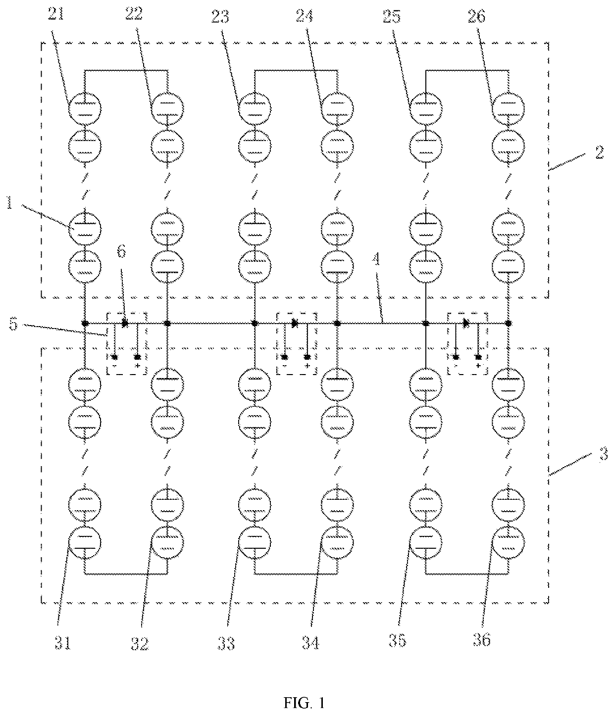
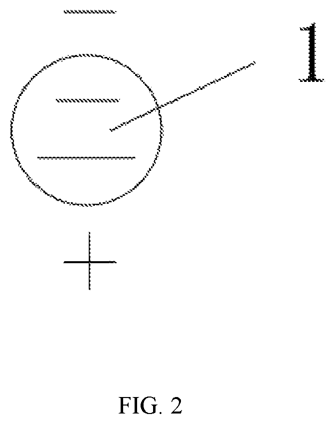
[0025]An internal protection circuit structure of photovoltaic modules having independent power generating unit includes a plurality of solar cells 1. As shown in FIG. 2 of the specification, a long line end in the solar cell 1 is a positive electrode, and a short line end is a negative electrode. A plurality of solar cells 1 are combined to form a power generating unit A ...


PUM

PropertyMeasurementUnit
polarityaaaaaaaaaa
power lossaaaaaaaaaa
output voltageaaaaaaaaaa

Abstract

The present invention discloses an internal protection circuit structure of photovoltaic modules having independent power generating unit, which includes a plurality of solar cells. The plurality of solar cells is combined to form a power generating unit A and a power generating unit B. Polarities of the upper ends of the substrings of solar cell are positive, negative, positive, negative, positive, and negative sequentially from the first column of A to the sixth column of A. Polarities of the lower ends of the substrings of solar cell are positive, negative, positive, negative, positive, and negative sequentially from the first column of B to the sixth column of B. Moreover, the busbar is provided with three separate junction boxes.

Description

CROSS REFERENCE TO RELATED APPLICATIONS[0001]This application is the national phase entry of International Application PCT / CN2017 / 099226, filed on Aug. 28, 2017, the entire content of which is incorporated herein by reference.TECHNICAL FIELD[0002]The present invention relates to the field of application technology of solar cell module encapsulation of solar crystalline silicon wafer, particularly to an internal protection circuit structure of photovoltaic modules having independent power generating unit.BACKGROUND[0003]With the accelerating energy consumption of conventional fossil fuels such as coal, oil, natural gas, etc., the eco-environment is continuously deteriorating. Especially, due to the greenhouse gas emissions, the global climate change is getting worse and worse. Therefore, the sustainable development of human society has been seriously threatened. Countries all around the world have formulated their own energy development strategies to cope with the limitations of conv...

Claims


Application Information

Patent Timeline
Patent Type & Authority Patents(United States)
IPC IPC(8): H02S40/34H01L31/044H01L31/02
CPCH02S40/34H01L31/02021H01L31/0201H01L31/044Y02E10/50
Inventor SUN, JUNJIANG, CHENGYINZHOU, FUSHENXIE, TAIHONGXIE, YI
Owner TONGWEI SOLAR HEFEI
Why Eureka
Try Eureka