Distributed switching system and method with time-based routing

a technology of distributed switching and time-based routing, which is applied in the direction of data switching networks, digital transmission, multiplex communication, etc., can solve the problems of inability to easily enhance to support multiple services or carry multimedia traffic, and the end-to-end transport requirements of real-time multimedia applications are major challenges that cannot be solved satisfactorily, so as to achieve low delay and jitter

Inactive Publication Date: 2005-04-26
SYNCHRODYNE
View PDF3 Cites 28 Cited by
  • Summary
  • Abstract
  • Description
  • Claims
  • Application Information

AI Technical Summary

Benefits of technology

[0026]The routing method that is disclosed in this invention is designed to operate with virtual pipe forwarding that carry real-time traffic over packet switching networks while guaranteeing end-to-end performance. This approach combines the advantages of both circuit and packet switching. It provides f

Problems solved by technology

However, the end-to-end transport requirements of real-time multimedia applications present a major challenge that cannot be solved satisfactorily by current networking technologies.
These characteristics and performance requirements are incompatible with the services that current circuit and packet switching networks can offer.
Circuit-switching networks, which are still the main carrier for real-time traffic, are designed for telephony service and cannot be easily enhanced to support multiple services or carry multimedia traffic.
However, since circuit-switching networks allocate resources exclusively for individual connections, they suffer from low utilization under bursty traffic.
Moreover, it is difficult to dynamically allocate circuits of widely different capacities, which makes it a challenge to support multimedia traffic.
However, current packet switches and routers operate asynchronously and provide best effort service only, in which end-to-end delay and jitter are neither guaranteed n

Method used


Image

  • Distributed switching system and method with time-based routing
  • Distributed switching system and method with time-based routing
  • Distributed switching system and method with time-based routing

Examples


Embodiment Construction

[0055]While this invention is susceptible of embodiment in many different forms, there is shown in the drawing, and will be described herein in detail, specific embodiments thereof with the understanding that the present disclosure is to be considered as an exemplification of the principles of the invention and is not intended to limit the invention to the specific embodiments illustrated.

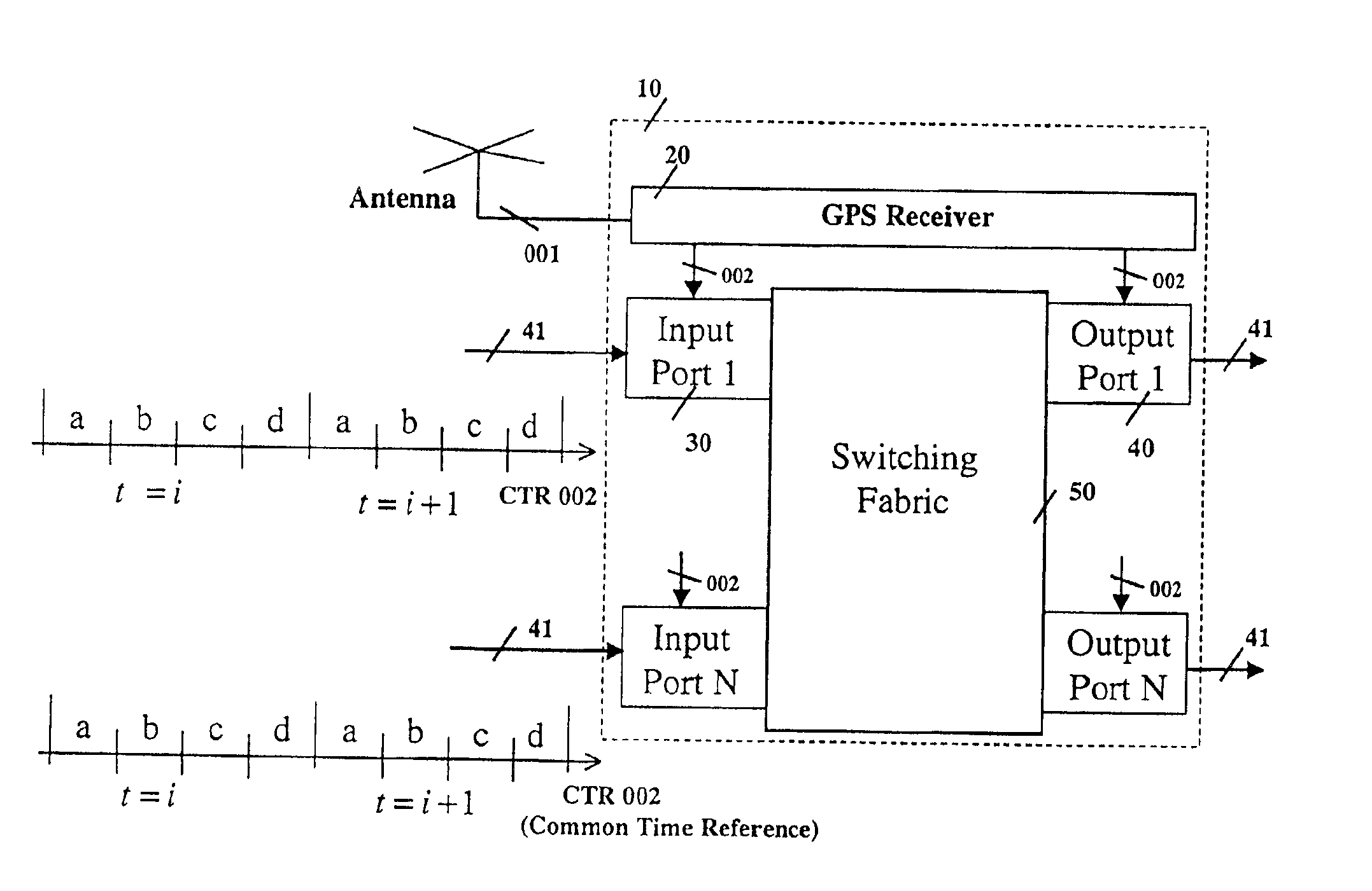
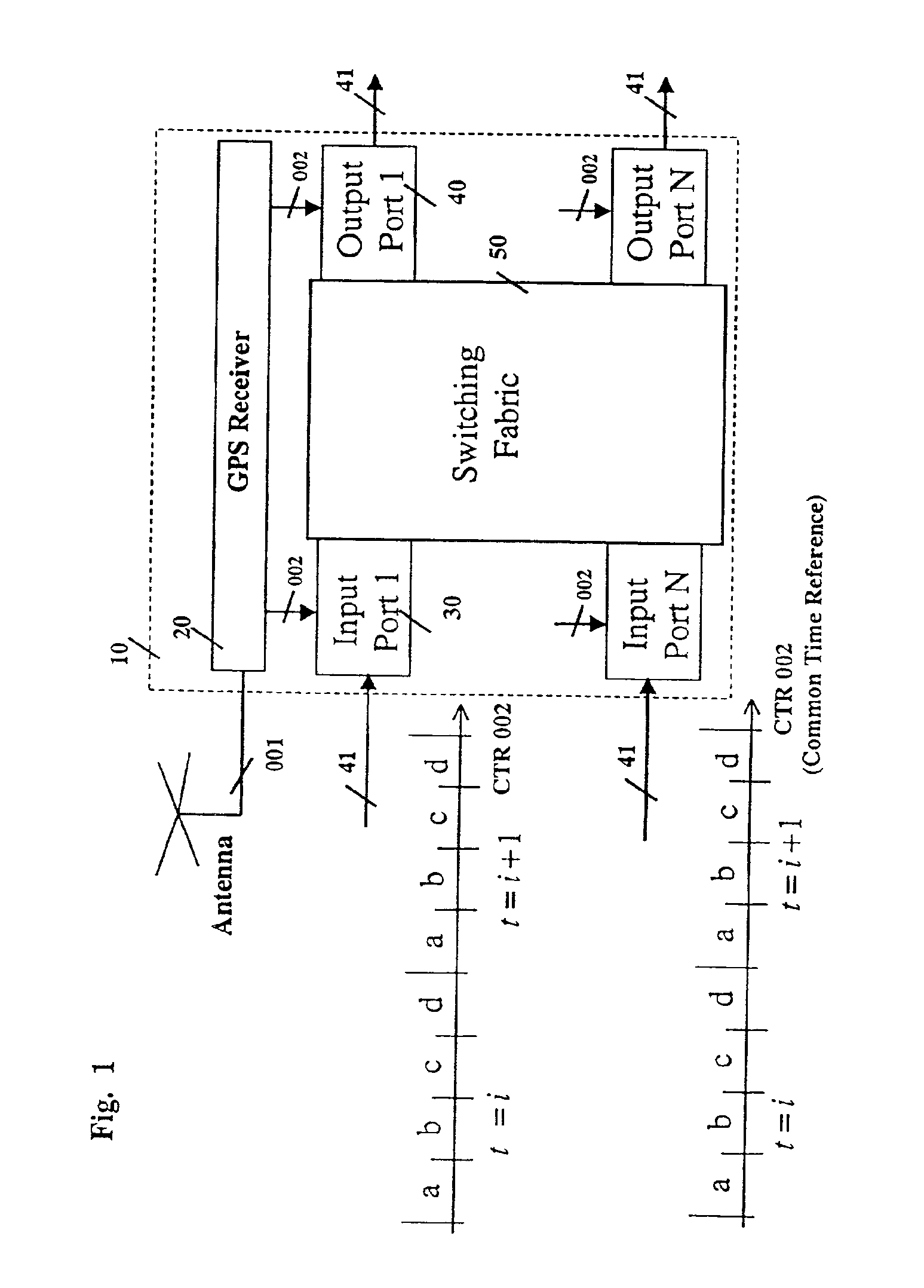
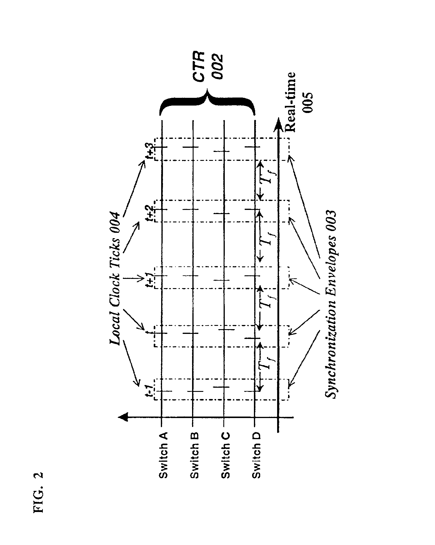
[0056]The present invention relates to a system and method for transmitting and forwarding packets over a packet switching network. The switches of the network maintain a common time reference, which is obtained either from an external source (such as GPS—Global Positioning System) or is generated and distributed internally. The time intervals are arranged in simple periodicity and complex periodicity (like seconds and minutes of a clock). A packet that arrives to an input port of a switch, is switched to an output port based on (i) its position within the predefined time interval and (ii) the uniq...


PUM


Abstract

This invention describes a method for transmitting and forwarding packets over a switching network using time information. The network switches maintain a common time reference, which is obtained either from an external source (such as GPS—Global Positioning System) or is generated and distributed internally. The time intervals are arranged in simple periodicity and complex periodicity (like seconds and minutes of a clock). A data packet that arrives to an input port is switched to an output port based on its order or time position in the time interval in which it arrives at the switch. The time interval duration can be longer than the time duration required for transmitting a data packet, in which case the exact position of a data packet in its forwarding time interval is predetermined.
This invention provides congestion-free data packet switching for data packets for which capacity in their corresponding forwarding links and time intervals is reserved in advance. Furthermore, such data packets reach their destination, which can be one or more (i.e., multicast) in predefined time intervals, which guarantees that the delay jitter is smaller than or equal to one time interval.

Description

RELATED APPLICATIONS[0001]This application is a divisional application filed, pursuant to 37 CFR §1.53(b), of copending, non-provisional patent application with Ser. No. 09 / 120,529, filed Jul. 22, 1998, which is incorporated herein by reference.BACKGROUND OF THE INVENTION[0002]This invention relates generally to a method and apparatus for transmitting of data on a communications network. More specifically, this invention provides timely forwarding and delivery of data over the network and to their destination nodes. Consequently, the end to-end performance parameters, such as, loss, delay and jitter, have either deterministic or probabilistic guarantees.[0003]This invention facilitates the routing of data packets using only time information that is globally available from the global positioning system (GPS). Consequently, over this novel communications network it is possible to transport wide variety of data packets, such as, IP (Internet protocol) and ATM (asynchronous transfer mod...

Claims


Application Information

Patent Timeline
IPC IPC(8): H04L29/06H04L12/56H04L12/64H04J3/06
CPCH04J3/0697H04L12/6418H04L47/10H04L47/22H04L47/28H04L29/06H04J3/0644H04L69/28H04L9/40
Inventor OFEK, YORAMSHACHAM, NACHUM
Owner SYNCHRODYNE
Why Eureka
Try Eureka