Adjusting structure of reflector and projecting apparatus

a technology of projecting apparatus and reflector, which is applied in the direction of projectors, instruments, mountings, etc., can solve the problems of less likely to ensure stability and accuracy, complicated and time-consuming adjusting structure of existing reflectors, etc., and achieves simple and time-saving operation, good adjusting stability and accuracy

Active Publication Date: 2020-05-05
CORETRONIC
View PDF5 Cites 0 Cited by
  • Summary
  • Abstract
  • Description
  • Claims
  • Application Information

AI Technical Summary

Benefits of technology

[0006]The present invention provides an adjusting structure of reflector. The adjusting structure of reflector is simple and time-saving in operation, and can achieve good adjusting stability and accuracy.
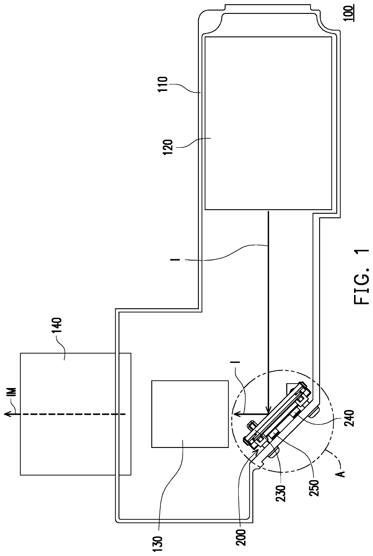
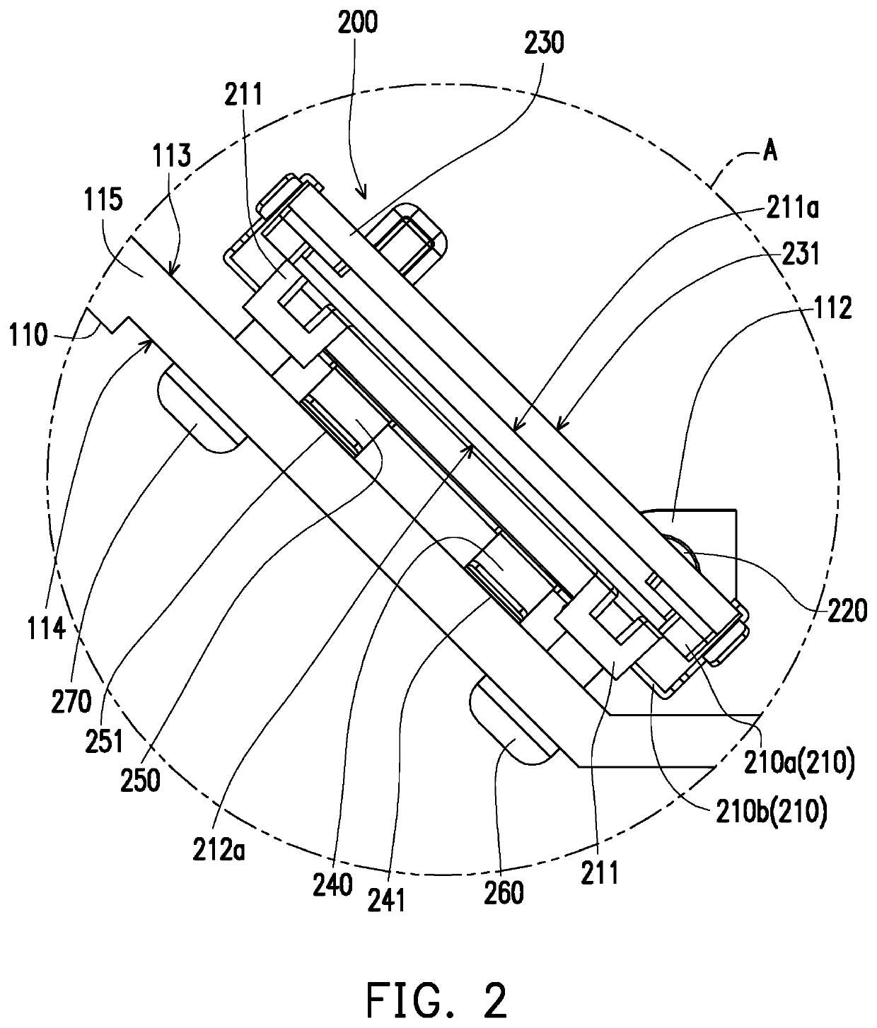
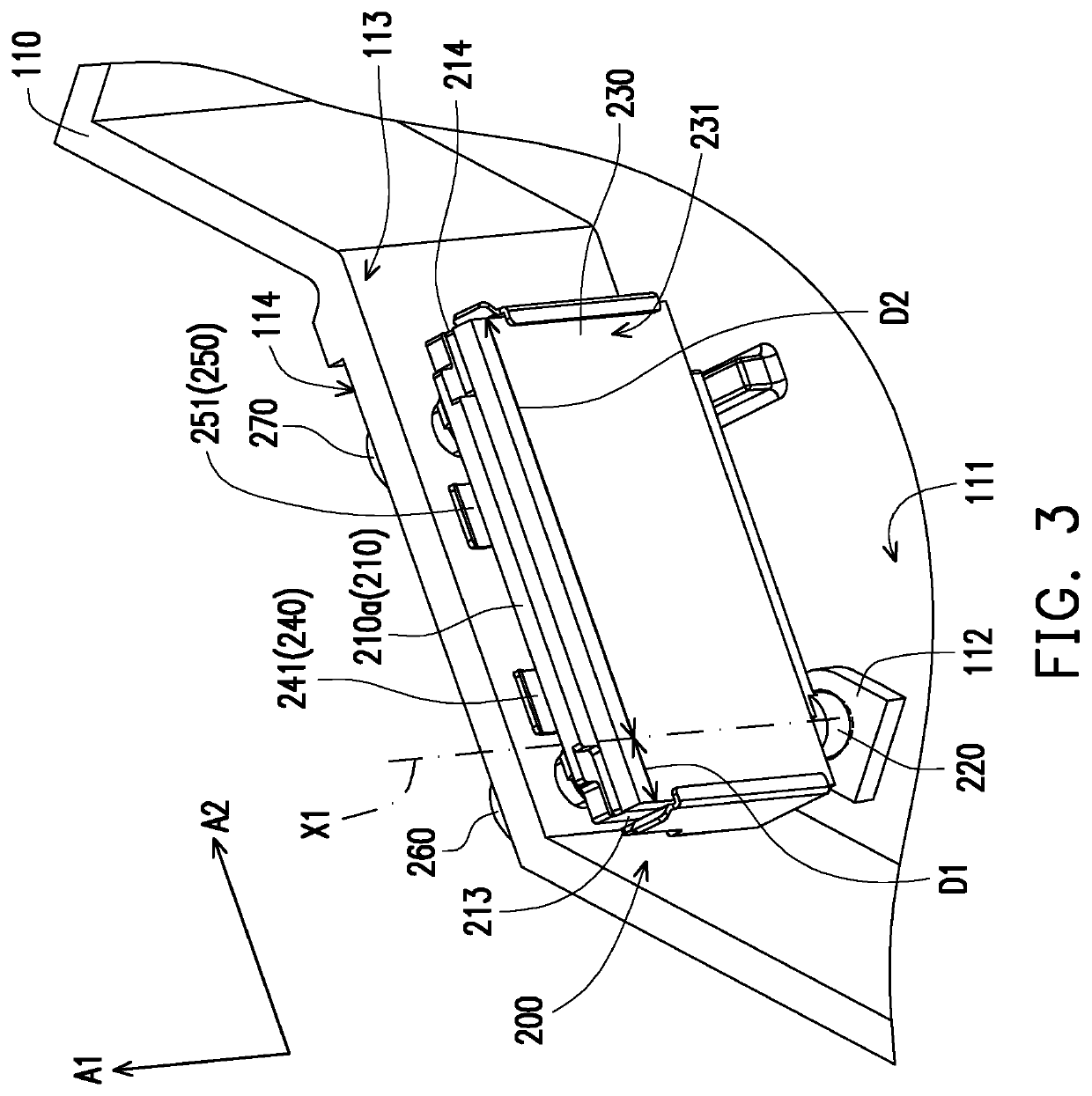
[0010]Based on the above, the embodiments of the present invention have at least one of the following advantages or effects. In the embodiments of the present invention, the base is limited in the housing by the two adjusting screws. By rotatably adjusting either of the two adjusting screws, the base and the reflector on the base can be driven, so that the base and the reflector on the base may be rotated relative to the housing with respect to a rotating supporting point (namely, the pivoting component) around two different axes. With the adjustment of a position of the reflector, the illuminating beam deflected by the reflector to the imaging module may be changed in angle or position accordingly. In the process of adjusting the position of the reflector, the two adjusting screws do not need to be removed. Once the adjustment of the two rotatable adjusting screws is stopped, the positions of the base and the reflector on the base are also fixed accordingly. On the other hand, at least one elastic component and the two adjusting screws are disposed at the same side of the base, and the least one elastic component is configured to abut against the housing, thus improving the stability of the base and the reflector on the base relative with respect to the housing during the process of rotation. As a result, the rotation process of the base and the reflector on the base relative to the housing may also be more smoothly to be rotated. It is worth mentioning that the least one elastic component may include two elastic parts. In other words, the two elastic parts can be integrally formed into a single elastic component. In general, the coordination of the two adjusting screws and the elastic component not only can cause the adjustment process of the positions of the base and the reflector on the base to be more simple and more time-saving, but also can achieve good adjustment stability and accuracy.

Problems solved by technology

From the above content, an adjusting structure of the existing reflector is relatively complicated and time-consuming in operation, and is less likely to ensure the stability and accuracy during adjustment of the reflector.

Method used


Image

  • Adjusting structure of reflector and projecting apparatus
  • Adjusting structure of reflector and projecting apparatus
  • Adjusting structure of reflector and projecting apparatus

Examples


Embodiment Construction

[0018]In the following detailed description of the preferred embodiments, reference is made to the accompanying drawings which form a part hereof, and in which are shown by way of illustration specific embodiments in which the invention may be practiced. In this regard, directional terminology, such as “top,”“bottom,”“front,”“back,” etc., is used with reference to the orientation of the Figure(s) being described. The components of the present invention can be positioned in a number of different orientations. As such, the directional terminology is used for purposes of illustration and is in no way limiting. On the other hand, the drawings are only schematic and the sizes of components may be exaggerated for clarity. It is to be understood that other embodiments may be utilized and structural changes may be made without departing from the scope of the present invention. Also, it is to be understood that the phraseology and terminology used herein are for the purpose of description an...


PUM


Abstract

An adjusting structure of reflector includes a base, a pivoting component, a reflector, a first adjusting screw and a second adjusting screw. The pivoting component is connected to the base, and the base is pivoted to a housing by using the pivoting component, and has freedoms of motion rotating around a first axial direction and a second axial direction perpendicular to the first axial direction. The reflector is disposed on the base. The first adjusting screw and the second adjusting screw are configured to be penetrated the housing and connected to the base. An adjusting direction of the first adjusting screw and the first axial direction may intersect with each other. The first adjusting screw and the second adjusting screw are located at the same side of the base. A projecting apparatus comprising the above adjusting structure of reflector is also provided.

Description

CROSS-REFERENCE TO RELATED APPLICATION[0001]This application claims the priority benefits of China applications serial no. 201810492991.8 filed on May 22, 2018 and 201822155627.0 filed on Dec. 21, 2018. The entireties of the above-mentioned patent applications are hereby incorporated by reference herein and made a part of this specification.BACKGROUND OF THE INVENTION1. Field of the Invention[0002]The invention relates to an adjusting structure of reflector and a projecting apparatus using the adjusting structure of reflector.2. Description of Related Art[0003]An existing projecting apparatus generally includes a light source module, an optical component group, an imaging module and a projection lens module. The optical component group is disposed between the light source module and the imaging module, and the imaging module is disposed between the optical component group and the projection lens module. Firstly, an illuminating beam emitted by the light source module may pass throug...

Claims


Application Information

Patent Timeline
Patent Type & Authority Patents(United States)
IPC IPC(8): G03B21/14G02B27/09G02B7/02
CPCG03B21/145G02B27/0977G03B21/142G02B7/022G02B26/0816G03B21/2066
Inventor LIU, MING-CHENTSENG, TSAN-FUWU, LIANG-WEI
Owner CORETRONIC
Why Eureka
Try Eureka