Check patentability & draft patents in minutes with Patsnap Eureka AI!

Charging connector, terminal fitting and method of fixing a sensor to a terminal fitting

a technology of charging connector and terminal fitting, which is applied in the direction of connection, electrical apparatus, coupling device connection, etc., can solve the problems of high current flow, damage to charging connector or other components, hot and hot wires, etc., and achieves good thermal conductivity, effective and simple mounting of sensors, and increased heat dissipation

Active Publication Date: 2020-05-05
SUMITOMO WIRING SYST LTD
View PDF18 Cites 6 Cited by
  • Summary
  • Abstract
  • Description
  • Claims
  • Application Information

AI Technical Summary

Benefits of technology

[0008]Mounting the sensor to the terminal fitting by at least one shrinking tube enables a condition of the terminal fitting, such as a temperature, vibration and / or humidity, to be detected precisely in an easy and reliable manner. In other words, the sensor is in abutment or contact with the terminal fitting such that the close disposition of the sensor and / or the direct contact of the sensor with the terminal fitting by means of the shrinking tube leads to a precise and reliable detection of the condition of the terminal fitting. Moreover, the shrinking tube allows easy mechanically affixation of the sensor to the terminal fitting thereby allowing a good direct or indirect coupling thereof to the terminal fitting to achieve a reliable sensing by the sensor.
[0025]Accordingly, a good thermal coupling between the terminal fitting (particularly its outer surface) and the sensor can be achieved by increasing the surface and / or mass achieving the thermal heat transfer to the sensor, thereby improving the measuring accuracy of the sensor (particularly of a temperature sensor).

Problems solved by technology

High currents may flow when charging the battery.
Thus, the charging connector and a wire might get hot.
A high temperature of the wire and the charging connector increase an electric resistance and might even damage the charging connector or the wire or other components.
However, restricting the charging current to a low value extends a charging time and decreases operational convenience of the vehicle.

Method used


Image

  • Charging connector, terminal fitting and method of fixing a sensor to a terminal fitting
  • Charging connector, terminal fitting and method of fixing a sensor to a terminal fitting
  • Charging connector, terminal fitting and method of fixing a sensor to a terminal fitting

Examples


first embodiment

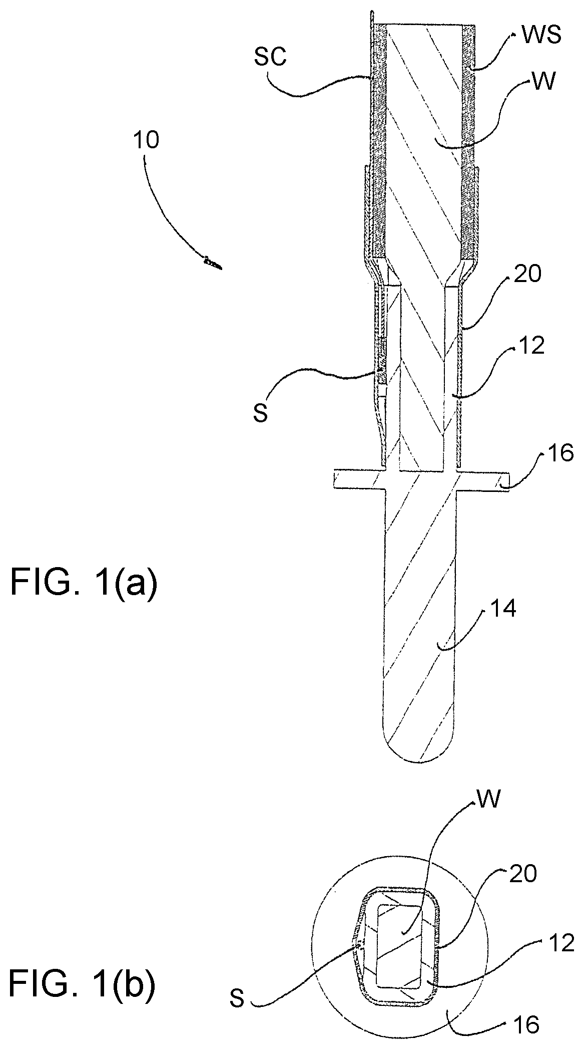
[0043]A first embodiment will be described with reference to FIGS. 1a and 1b. FIG. 1a is a longitudinal cross-sectional view of a terminal fitting 10 comprising a sensor S. FIG. 1b is a cross-sectional view of the terminal fitting 10 perpendicular to a longitudinal axis of the terminal fitting 10 in the area of the sensor S.

[0044]As shown in FIG. 1, the terminal fitting 10 comprises wire connection portion (particularly comprising at least one crimping, welding and / or soldering part 12) at or near a back side of the terminal fitting 10 so as to connect the terminal fitting 10 with a wire W of a cable. To connect the wire W with the terminal fitting 10, a wire sheathing WS is removed e.g. at a tip part of the wire W. The exposed wire W arranged at the wire connection portion is inserted into the crimping, welding and / or soldering part 12 of the terminal fitting 10. Subsequently, the arranged (inserted) part of wire W is electrically connected to the wire connection portion, particula...

second embodiment

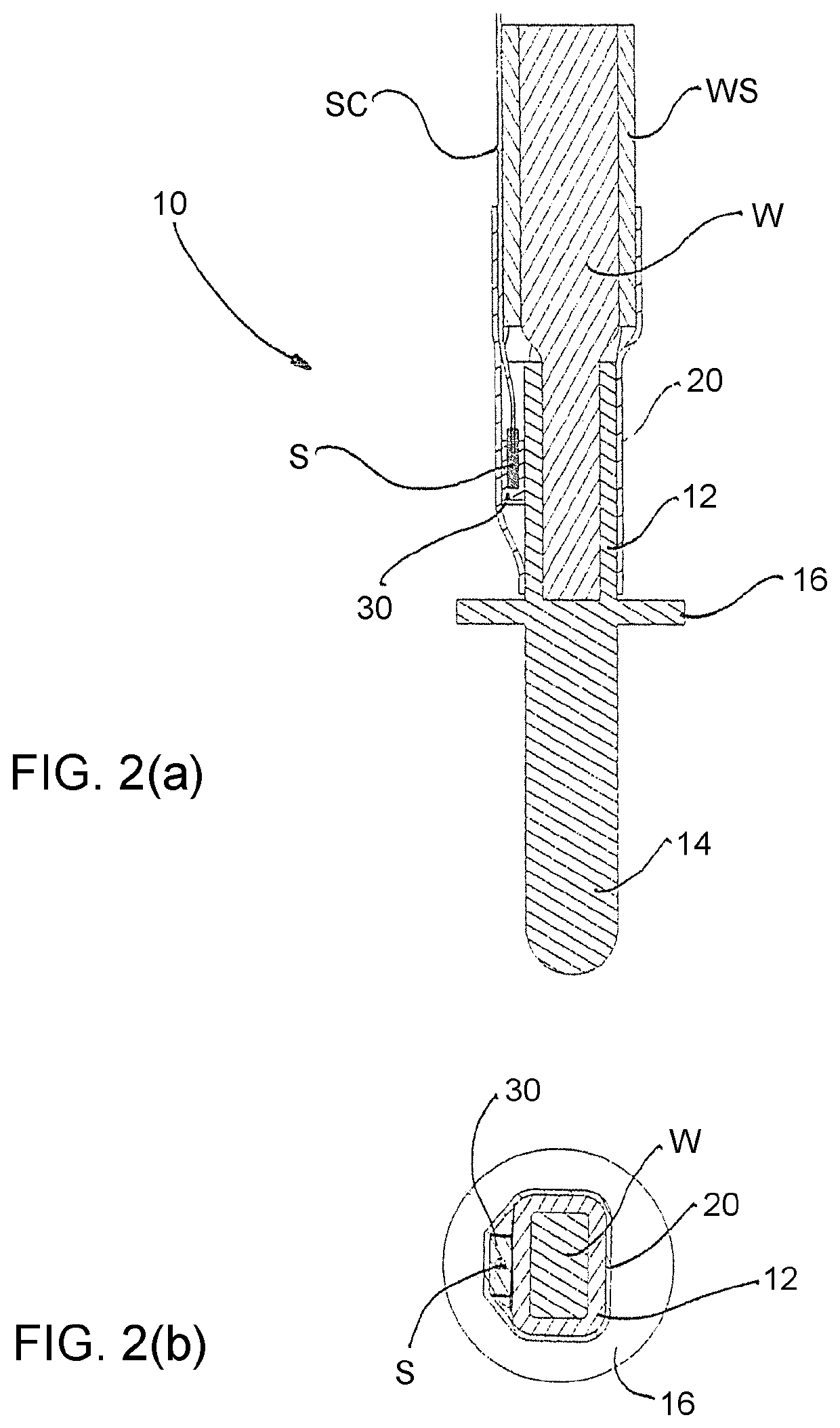
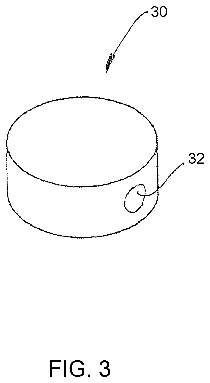
[0052]In the second embodiment, the sensor S is also mounted to the terminal fitting 10, particularly to an outer surface of the wire connection portion (particularly the crimping, welding and / or soldering part 12) of the terminal fitting 10. However, a mounting bracket 30, as shown in FIG. 3 is used as a particular thermal (or heat) coupling member to fix or mount the sensor S onto the terminal fitting 10. The mounting bracket 30 particularly is of a substantially circular or disk-shaped form and / or comprises a mounting hole 32 particularly at an outer circumference thereof.

[0053]The sensor S at least partly is placed or inserted within the mounting hole 32 of the mounting bracket 30 (and particularly secured therein by press-fitting and / or by means of an adhesive or the like specifically having appropriate thermal conductivity properties) before placing the sensor S onto the terminal fitting 10, particularly the outer surface of the crimping, welding and / or soldering part 12. Acco...


PUM


Abstract

A charging connector for charging a battery installed in a vehicle includes a housing (51) with at least one accommodating chamber (64a) for at least partly accommodating at least one terminal fitting (10), and at least one sensor (S) mounted to at least one terminal fitting (10) by a shrinking tube (20). A corresponding method and a corresponding terminal fitting (10) also are provided.

Description

BACKGROUNDField of the Invention[0001]The invention relates to a charging connector for charging a battery installed in a vehicle, in particular for an electric driven vehicle or a hybrid vehicle. Further, the invention relates to a terminal fitting to be applied in a charging connector and to a method of fixing a sensor to a terminal fitting.Description of the Related Art[0002]Electric vehicles contribute to cleaner air in cities because they produce no harmful emissions. An electric vehicle (EV) recharged from the US grid electricity in 2008 emits about 115 grams of CO2 per kilometer, whereas a conventional US-market gasoline powered car emits about 250 grams of CO2 per kilometer. The concept “Vehicle to Grid” provides electric cars and hybrid vehicles as an energy reservoir for the public power grid. In this concept, vehicles are parked most of the time in their life, and may be used as an energy source and accumulator to compensate for peak loads in the public power grid. This c...

Claims


Application Information

Patent Timeline
Patent Type & Authority Patents(United States)
IPC IPC(8): H01R13/66H01R4/72
CPCH01R4/72H01R13/6683H01R2201/26
Inventor SHIMIZU, TOORUSCHMIDT, HEIKO
Owner SUMITOMO WIRING SYST LTD
Features
  • R&D
  • Intellectual Property
  • Life Sciences
  • Materials
  • Tech Scout
  • Unparalleled Data Quality
  • Higher Quality Content
  • 60% Fewer Hallucinations
Learn More