Micromechanical sound transducer

a sound transducer and micro-mechanical technology, applied in the direction of diaphragm construction, electrostatic transducers of semiconductor, loudspeakers, etc., can solve the problems of unregulated movement of the membrane, low efficiency, and high power consumption of often times more than one watt, so as to achieve more precise and reliable detection

Active Publication Date: 2020-03-26
FRAUNHOFER GESELLSCHAFT ZUR FOERDERUNG DER ANGEWANDTEN FORSCHUNG EV
View PDF0 Cites 15 Cited by
  • Summary
  • Abstract
  • Description
  • Claims
  • Application Information

AI Technical Summary

Benefits of technology

[0020]According to an embodiment, the diaphragm element may comprise a varying geometry (e.g. a geometry that is curved / tiled towards the actuator) in its cross section so that the slit mostly has a constant cross section along the actuator movement. According to embodiments, the diaphragm may form a mechanical stop to prevent a mechanical overload.
[0021]A further embodiment provides a micromechanical sound transducer that includes a controller which drives the second bending actuator such that it is excited to vibrate in-phase with the first bending actuator. In addition, according to a further embodiment, it may be advantageous to provide a sensor system that senses the vibration and / or position of the first and / or second bending actuator to allow the controller to drive the two bending actuators in-phase. In contrast to conventional systems that mostly do not have a sensor system and that only sense the deflection of the drive (not only the membrane), in this principle, the actual position of the sound-generating element may be easily determined by means of a well-integrable sensor system. This is very advantageous and allows for a significantly more precise and reliable detection. This forms the basis for a regulated excitation (closed-loop) which may electronically compensate for external influences, aging effects and nonlinearities.

Problems solved by technology

A significant disadvantage of these conventional electrodynamic sound transducers is their low efficiency and the resulting high power consumption of often times more than one watt.
In addition, such sound transducers do not comprise any position sensor systems, so that the movement of the membrane is unregulated and large distortions occur at higher sound pressure levels.
Further disadvantages are large series deviations as well as large height dimensions of often times more than 3 mm.
However, it still is a fundamental problem that the sound pressure levels of MEMS sound transducers are too low.
The primary reason for this is the difficulty to generate sufficiently large stroke movements with dimensions that are as small as possible.
A further complicating factor is that in order to prevent an acoustic short circuit, a membrane is needed which has a negative effect on the overall deflection due to its additional spring stiffness.
The latter may be minimized by using very soft and three-dimensionally shaped membranes (e.g. having a torus), which, however, may currently not be manufactured using MEMS technology and may therefore only be integrated in a complex and costly hybrid manner.
Publications and patent specifications concern MEMS sound transducers of different implementations, which has not resulted in market-ready products due to, inter alia, the above-mentioned problems.
Here, piezoelectric materials such as PZT, AlN or ZnO are directly applied onto silicon-based sound transducer membranes, however, which do not allow for sufficiently large deflections due to their low elasticity.
In addition, nonlinearities only occur at significantly larger movement amplitudes.

Method used


Image

  • Micromechanical sound transducer
  • Micromechanical sound transducer
  • Micromechanical sound transducer

Examples


Embodiment Construction

[0047]Before embodiments of the present invention are subsequently described in more detail based on the drawings, it is to be noted that elements and structures with the same effect are provided with the same reference numerals so that their description is may be applied to each other and may be interchanged with each other.

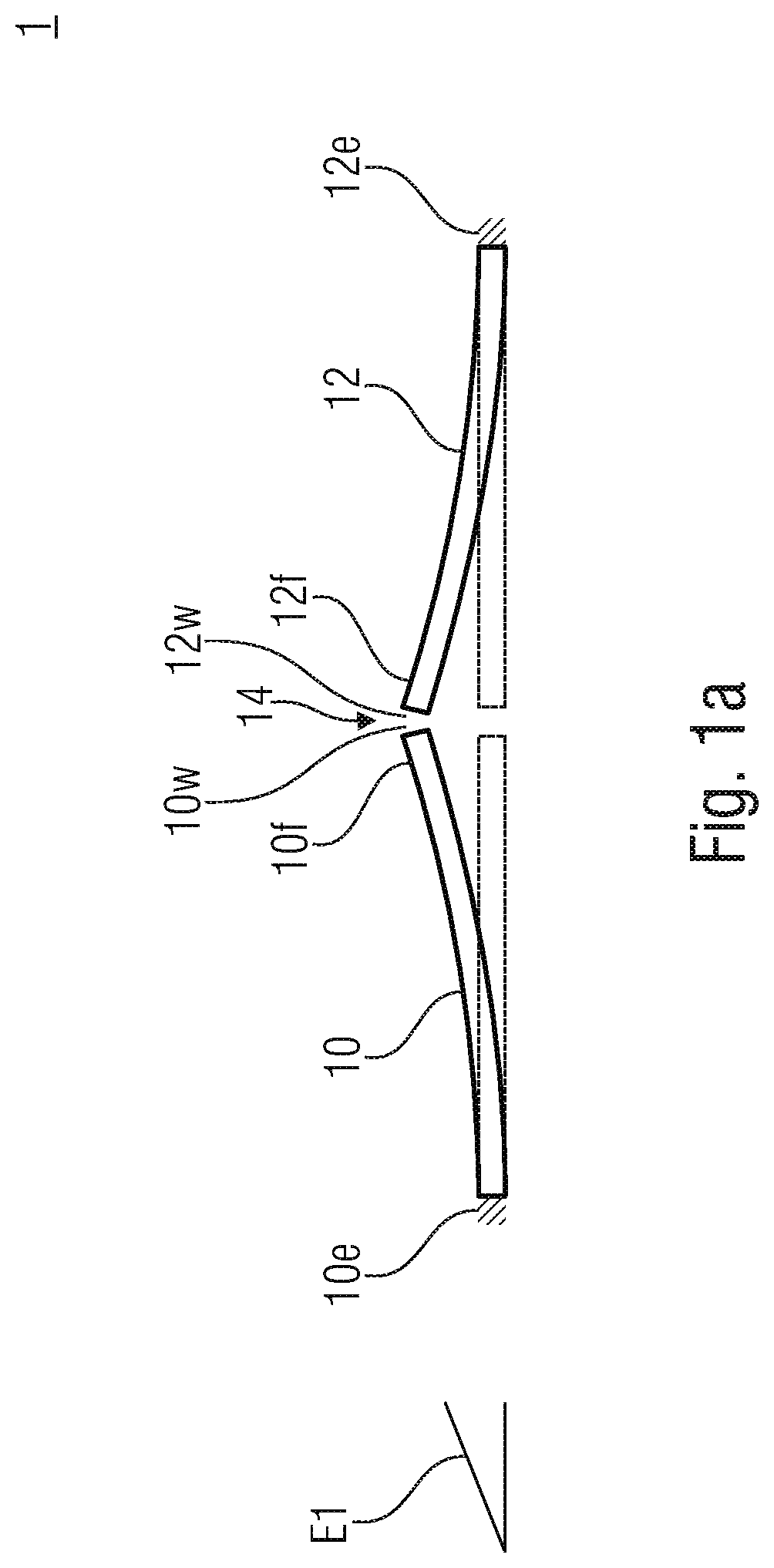
[0048]FIG. 1a shows a sound transducer 1 with a first bending actuator 10 and a second bending actuator 12. Both are arranged, or clamped in, in a plane E1, as can be seen based on the clampings 10e and 12e. The clamping may be realized by the bending actuators 10 and 12 being etched out from a mutual substrate (not illustrated) so that the bending actuators 10 and 12 are connected to the substrate on one side, and by a (mutual) cavity (no illustrated) being formed below the actuators 10 and 12. At this point, it is to be noted that the illustrated bending actuators 10 and 12 may be biased, for example, so that the illustration either shows an idle state or a de...


PUM


Abstract

A micromechanical sound transducer according to a first aspect includes a first bending transducer with a free end and a second bending transducer with a free end, the two bending transducers being arranged in a mutual plane, wherein the free end of the first bending transducer is separated from the free end of the second bending transducer via a slit. The second bending transducer is excited in-phase with the vertical vibration of the first bending transducer. A micromechanical sound transducer according to a second aspect includes a first bending transducer that is excited to vibrate vertically and a diaphragm element extending vertically to the first bending transducer, the diaphragm element being separated from a free end of the first bending transducer via a slit.

Description

CROSS-REFERENCES TO RELATED APPLICATIONS[0001]This application is a continuation of copending International Application No. PCT / EP2018 / 063961, filed May 28, 2018, which is incorporated herein by reference in its entirety, and additionally claims priority from German Applications No. DE 10 2017 208 911.3, filed May 26, 2017, which is incorporated herein by reference in its entirety.BACKGROUND OF THE INVENTION[0002]Embodiments of the present invention refers to a micromechanical sound transducer with at least one bending actuator (in general: bending transducer) and a miniaturized slit as well as to a miniaturized sound transducer having a cascaded bending transducer. Additional embodiments concern corresponding manufacturing methods.[0003]Although MEMS are used in almost all areas, miniaturized sound transducers are still manufactured using precision engineering. These so-called “micro-speakers” are based on an electrodynamic driving systems wherein a membrane is deflected by a movin...

Claims


Application Information

Patent Timeline
Patent Type & Authority Applications(United States)
IPC IPC(8): H04R17/00H04R7/06H04R7/26
CPCH04R17/00H04R7/26H04R7/06H04R7/10H04R19/005H04R19/02H04R19/04H04R31/003H04R2201/003H04R2440/01H04R2499/11
Inventor STOPPEL, FABIANWAGNER, BERNHARDGU-STOPPEL, SHANSHAN
Owner FRAUNHOFER GESELLSCHAFT ZUR FOERDERUNG DER ANGEWANDTEN FORSCHUNG EV
Why Eureka
Try Eureka