Receiving apparatus and synchronising method for a digital telecommunication system

a technology of receiving apparatus and digital telecommunication system, which is applied in the direction of synchronisation signal speed/phase control, amplitude demodulation, operating means/releasing devices of valves, etc., can solve problems such as synchronisation failure, and achieve the effect of effective and sophisticated synchronisation mechanism

Inactive Publication Date: 2006-11-30
REDWOOD TECHNOLOGIES LLC
View PDF11 Cites 15 Cited by
  • Summary
  • Abstract
  • Description
  • Claims
  • Application Information

AI Technical Summary

Benefits of technology

[0024] According to another aspect of the present invention, the cross correlation means has a cross correlation window length corresponding to the length of two repetition patterns for detecting the position of the cross correlation peak. The cross correlation means of the further aspect of the present invention thus directly cross correlates received data signals on the basis of the leng

Problems solved by technology

On the other hand, if one of the cross correlation pea

Method used


Image

  • Receiving apparatus and synchronising method for a digital telecommunication system
  • Receiving apparatus and synchronising method for a digital telecommunication system
  • Receiving apparatus and synchronising method for a digital telecommunication system

Examples


first embodiment

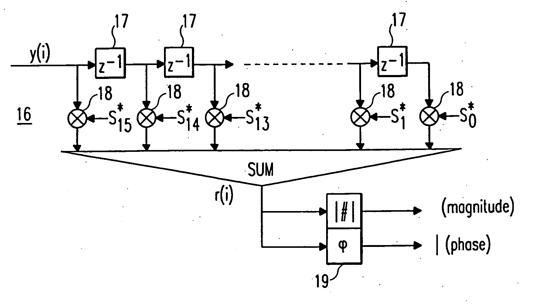
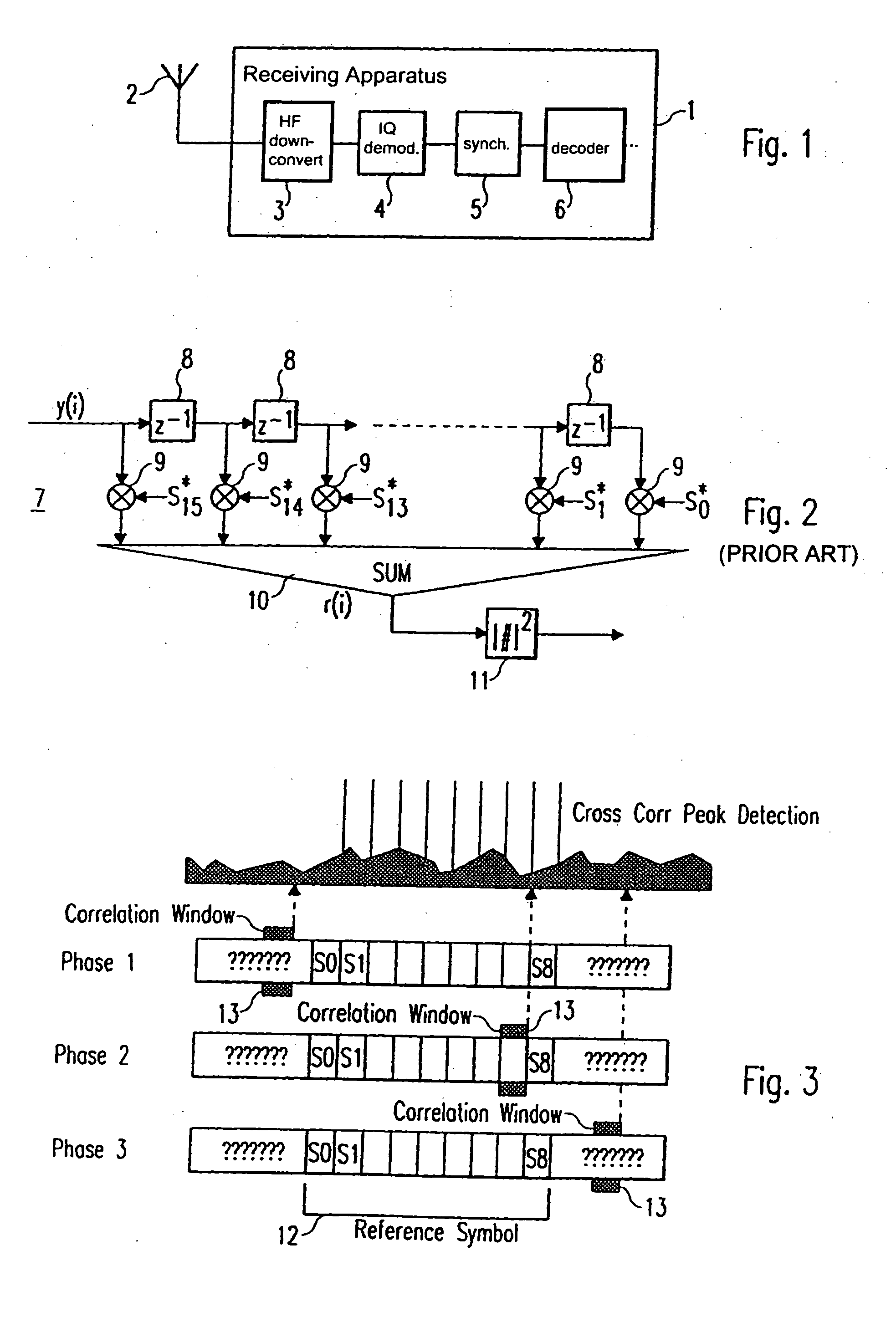
[0046] In FIG. 6, a cross correlation means 16 and a detection means 19 are shown, which can be implemented in a synchronising means 5 of a receiving apparatus 1 of the present invention, the general structure of which is shown in FIG. 1. The structure of the cross correlation means 16 is identical to the structure of the cross correlation means 7 shown in FIG. 2, so that a detailed explanation is omitted. The cross correlation means 16 comprises 15 delay means 17 and 16 multiplication means 18 as well as a sum means for adding the outputs of the multiplication means 18. The cross correlation window length of the cross correlation means 16 corresponds to the length of one repetition pattern, which is e. g. 16 samples. A received data stream of 16 samples is cross correlated with complex conjugated samples of an expected repetition pattern stored in the receiving apparatus 1. The output signal r(i) of the sum means, i.e. the output signal of the cross correlation means 16 is supplied...

second embodiment

[0052] In FIG. 11, a cross correlation means 24 is shown, which can be implemented in a synchronising means 5 of a receiving apparatus 1 of the present invention, a general structure of which is e. g. shown in FIG. 1.

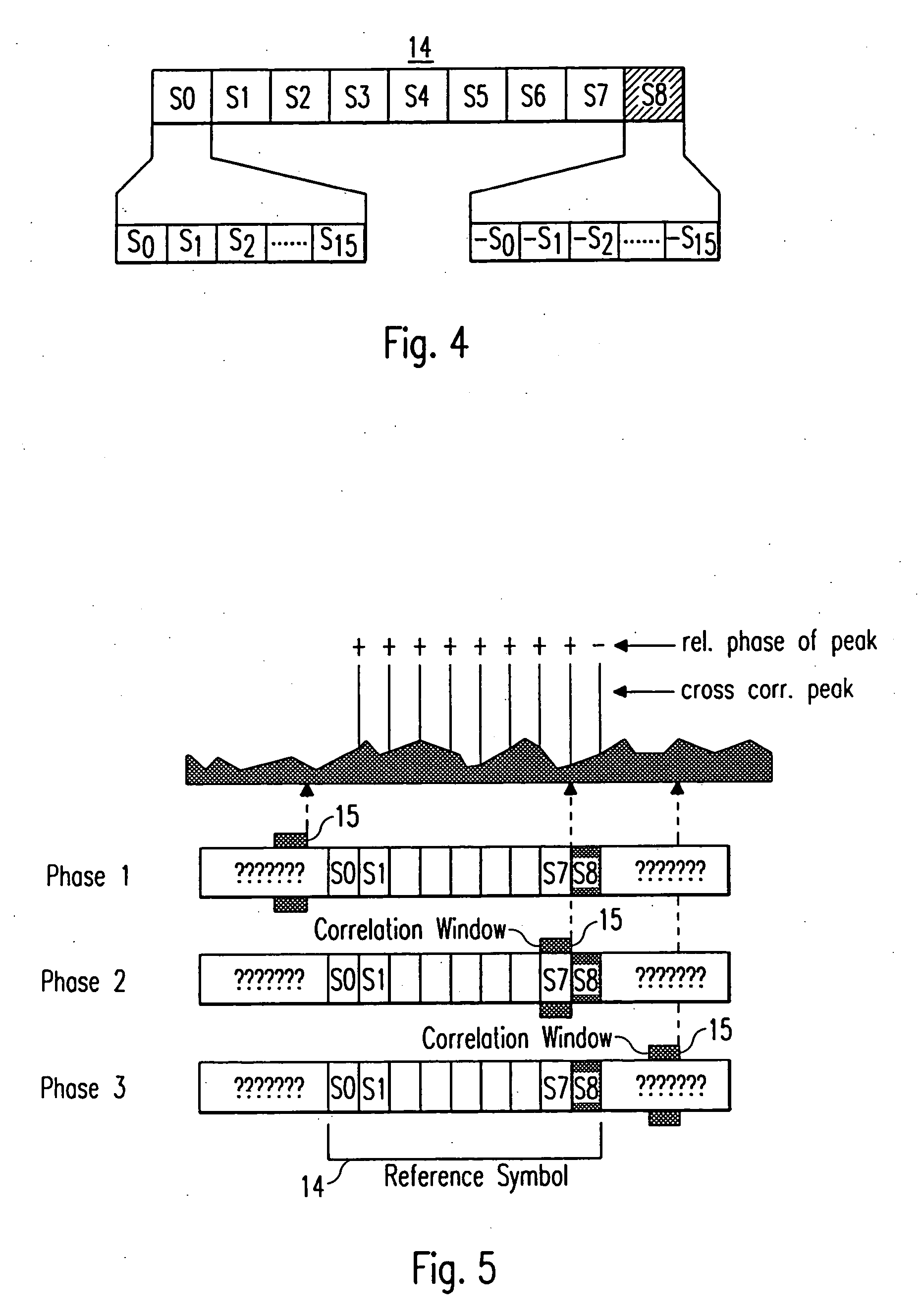
[0053] The cross correlation means 24 essentially has the same structure as the cross correlation means 16 shown in FIG. 6 and the cross correlation means 7 shown in FIG. 2. The main difference is, that the cross correlation means 24 shown in FIG. 11 has a cross correlation window length of two repetition patterns, which in the shown example corresponds to 32 samples, when the structure of the reference symbol shown in FIG. 4 is assumed. Thereby, the cross correlation means 24 comprises 31 delay means 25, which are arranged serially and respectively cause a delay of one sample. Further, the cross correlation means 24 comprises 32 multiplication means, which multiply the respective (delayed) samples of the received signal y(i) with stored positive and negative complex co...


PUM


Abstract

A receiving apparatus (1) for receiving signals in a digital telecommunication system and a synchronizing method for synchronizing the receiving apparatus (1). The receiving apparatus (1) includes a receiver (2, 3) for receiving a reference symbol having at least two repetition patterns. One of the, repetition patterns is phase-shifted in relation to the other. The receiving apparatus (1) is synchronized in the digital telecommunication system using the received reference symbol. The synchronization includes a cross correlation of at least one of two repetition patterns within a cross correlation window having a predetermined length. In this manner, the performance and the accuracy of a cross correlation peak detection can be enhanced for improved synchronization.

Description

CROSS-REFERENCE TO RELATED APPLICATIONS [0001] This application is a Divisional Application of, and claims the benefit of priority under 35 U.S.C. §120 from, U.S. application Ser. No. 09 / 510,652, filed Feb. 22, 2000, and claims the benefit of priority under 35 U.S.C § 119 from European Patent Application No. 99103546.0, filed Feb. 24, 1999. The entire contents of each of the above applications are incorporated herein by reference.BACKGROUND OF THE INVENTION [0002] The present invention relates to a receiving apparatus for receiving signals in a digital telecommunication system and to a synchronising method for synchronising such a receiving apparatus. Particularly, the receiving apparatus and the synchronising method of the present invention use a cross correlation mechanism to achieve accurate time and frequency synchronisation. [0003] Digital telecommunication systems generally need a synchronisation of a transmitting side and a receiving side. The transmitting side and the receiv...

Claims


Application Information

Patent Timeline
IPC IPC(8): H04K1/10H04L27/06H04L7/00H04B7/26H04L7/08H04L7/04
CPCH04L7/046H04L7/041F16K37/0041F16K3/02F16K31/53
Inventor BOHNKE, RALFDOLLE, THOMASKONSCHAK, TINO
Owner REDWOOD TECHNOLOGIES LLC
Why Eureka
Try Eureka