Filter medium for an oil filter

a filter medium and oil technology, applied in the direction of filtration separation, cartridge filter, stationary filter element filter, etc., can solve the problems of low to moderate dirt pick-up capacity, low filtration efficiency, and low pressure loss,

Active Publication Date: 2020-05-12
IBS FILTRAN KUNST METALLERZEUGNISSE
View PDF27 Cites 0 Cited by
  • Summary
  • Abstract
  • Description
  • Claims
  • Application Information

AI Technical Summary

Benefits of technology

[0009]The filtration medium displays its advantageous effects in a particularly impressive manner when used in a suction filter with a filter medium according to one of the preceding claims.
[0010]In summary, the specific arrangement according to the invention leads as a result to the following advantages:
[0011]Low loss in pressure at low flow velocities and high viscosities (for example—30° C.).
[0013]Inhomogeneous charging of the open filter medium and homogeneous charging of the tight filter medium.
[0014]Reductions in overall height by approx. 100%-300% (compared to conventional multilayer filter media in the region of oil filters) to approx. 2-3 mm are possible at the same or even improved performance levels.
[0015]The precise behavior of the filter medium can be individually designed so as to be optimized for the particular application (as desired by the customer). Smart selection of the various filter media, hole diameters and grid spacer design and the ratios thereof is necessary and possible for this purpose. Using further filter layers having holes and further corresponding grid spacer it is possible to optimize the capacity and the filtration efficiency further.

Problems solved by technology

Previously known filter media in the region of oil filters have the drawback, on the one hand, that, on use of efficient filter media, in particular at low temperatures (pressure filter media), considerable losses in pressure occur at low to moderate dirt pick-up capacity.
Although low filtration media display an acceptable loss in pressure at high dirt pick-up capacity, they do not have high filtration efficiency.
And the known woven fabrics for filtration purposes also have only low dirt pick-up capacity and in addition do not attain high efficiency.
Specifically in the field of suction filters (maximum attainable reduced pressure of 1 bar), the foregoing problems hamper efficient and long-lasting filtration results.

Method used


Image

  • Filter medium for an oil filter
  • Filter medium for an oil filter
  • Filter medium for an oil filter

Examples


Embodiment Construction

[0027]The invention will now be described with reference to the drawing figures, in which like reference numerals refer to like parts throughout.

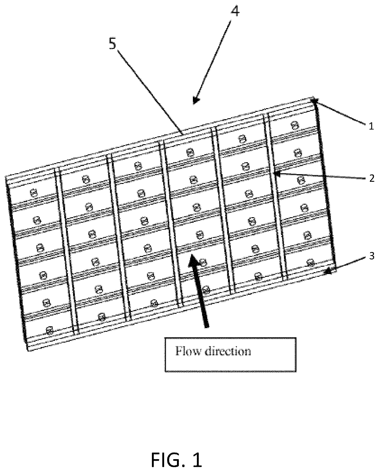
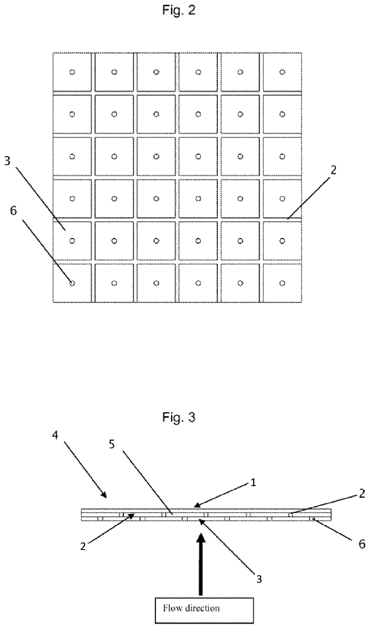
[0028]According to FIG. 1, the filter medium 4 comprises a first filtration layer 1 made of an open filter medium, a grid spacer 2 forming the intermediate chambers 5 in the surface of the filter medium 4, and a second filtration layer 3 made of a tight filter medium, a through-opening 6 being arranged in the second filtration layer 3 for each intermediate chamber. The first filtration layer 1, the grid spacer 2, forming the intermediate chambers 5, and the second filtration layer 3 are arranged on one another in a sandwich-like manner, the grid spacer being arranged between the two filtration layers 1 and 3 and setting said filtration layers apart from each other.

[0029]This sandwich construction may be seen particularly clearly from FIG. 3. The arrangement of the grid spacer 2 between the two filtration layers 1 and 3 forms the intermediat...


PUM

PropertyMeasurementUnit
diameteraaaaaaaaaa
pressureaaaaaaaaaa
temperaturesaaaaaaaaaa

Abstract

A filter medium for the filtration of oil, in particular in the oil circuit of gear mechanisms and internal combustion engines, comprises a first and a second filtration layer, the first filtration layer comprising an open filtration medium and being arranged on the second filtration layer comprising a tight filtration medium, an intermediate chamber being arranged between the first and the second filtration layer, so that the first and the second filtration layer are set apart from each other in the region of the intermediate chamber in the direction of filtration.

Description

CROSS-REFERENCE TO RELATED APPLICATIONS[0001]This application claims priority to foreign Patent Application DE 10 2008 027 663.4, filed on Jun. 10, 2008, the disclosure of which is incorporated herein by reference in its entirety.FIELD OF THE INVENTION[0002]The present invention relates to a filter medium. More particularly, the present invention relates to a filter medium for the filtration of oil.BACKGROUND OF THE INVENTION[0003]Previously known filter media in the region of oil filters have the drawback, on the one hand, that, on use of efficient filter media, in particular at low temperatures (pressure filter media), considerable losses in pressure occur at low to moderate dirt pick-up capacity. Although low filtration media display an acceptable loss in pressure at high dirt pick-up capacity, they do not have high filtration efficiency. And the known woven fabrics for filtration purposes also have only low dirt pick-up capacity and in addition do not attain high efficiency. Spe...

Claims


Application Information

Patent Timeline
Patent Type & Authority Patents(United States)
IPC IPC(8): F01M11/03B01D29/01B01D29/56
CPCB01D29/01B01D29/56B01D2201/04B01D39/00B01D27/00B01D35/00B01D39/14
Inventor DEDERING, MICHAEL
Owner IBS FILTRAN KUNST METALLERZEUGNISSE
Why Eureka
Try Eureka