Vapour deposition process for the preparation of a chemical compound

a chemical compound and vapour deposition technology, which is applied in the direction of cell components, final product manufacturing, sustainable manufacturing/processing, etc., can solve the problems of difficult control and significant difficulties in the exact composition of the thin film thereby produced, and achieve the effect of facilitating discovery and promoting in-situ crystallisation in the film

Active Publication Date: 2015-06-30
ILIKA TECH LTD +1
View PDF13 Cites 2 Cited by
  • Summary
  • Abstract
  • Description
  • Claims
  • Application Information

AI Technical Summary

Benefits of technology

[0067]A key advantage of the present invention is that, since each component element of the chemical compound is provided separately as a vapour, it is possible to control the evaporation rate, and thus deposition rate, of each component element separately. Accordingly, by controlling the deposition rates of each the component element vapours, the present invention allows the stoichiometry of the chemical compound to be controlled. Thus, according to a preferred embodiment of the present invention, the stoichiometry of the chemical compound is controlled by controlling the rate of deposition of each component element onto the substrate.
[0068]The means by which the rate of deposition is controlled will depend upon the type of source being used. In the case of an effusion cell, the rate of deposition is controlled by the temperature of the cell, which is both stable and reproducible. In the case of an electron beam evaporator source, the power applied to the sample controls the deposition rate. In the case of plasma sources, the flow rate and plasma power control the deposition rate. In the case of cracking sources, such as phosphorus crackers, the deposition rate is controlled by controlling the flow rate and by controlling the temperature (for example of the cracking zone). Controlling the temperature of the cracking zone in a cracking source also allows the composition of the beam to be controlled (for example, the amount of P2 compared to P4 in a phosphorus beam).
[0069]According to another advantageous embodiment of the present invention, one or more of the component elements is / are deposited on the substrate with a concentration that varies across at least a portion of the substrate. This embodiment allows a series of chemical compounds having different stoichiometries to be prepared on said portion of the substrate. This offers the opportunity to prepare and analyse a library of chemical compounds, thereby enabling discovery of a chemical compound which is optimised for a particular application. Once the optimised compound has been discovered, it may be produced according to the present invention by setting the deposition rates of the component elements accordingly. It is envisaged that this technique will facilitate discovery of a range of new and useful thin film materials, such as battery materials.
[0070]In order to deposit one or more of the component elements on the substrate with a concentration (thickness) that varies across at least a portion of the substrate, so-called “wedge shutters” may be employed to partially block the path between a given source and the substrate. The use of wedge shutters in this way is known in the art. According to a particularly advantageous arrangement, it is known that wedge shutters can be positioned between a source and a substrate such that the concentration of the vapour deposited on the substrate varies in a linear manner across the whole surface of the substrate, i.e. avoiding areas of no deposition or of constant deposition (plateaus). This arrangement is described in Guerin, S; Hayden, B. E., J. Comb. Chem 2006, 8, 66 and WO 2005 / 035820, the entire content of both of which is incorporated herein by reference.
[0071]The “as-deposited” materials prepared according to the present invention are generally amorphous to X-Rays, and can be partly or completely crystallised using ex-situ annealing treatments. Thus, according to an embodiment of the present invention, annealing is carried out following deposition. It is also possible to deposit onto heated substrates, which promotes in-situ crystallisation in the films. Thus, an embodiment of the present invention employs a heated substrate.
[0072]Although it is believed that the process of the present invention will find use in a wide range of applications, it is believed that it may find particular utility in the preparation of batteries, and in particular in the manufacture of thin-film electrolytes and / or electrodes. Thus, according to a second aspect, the present invention provides a process for the manufacture of a battery, wherein the process includes the vapour deposition process according to the present invention. In a preferred embodiment, the battery is a lithium ion battery.

Problems solved by technology

As a consequence, it is often difficult to control the exact composition of the thin films thereby produced.
This lack of control presents significant difficulties when trying to optimise the composition of thin films, and also when trying to reliably reproduce thin films of a particular composition.

Method used


Image

  • Vapour deposition process for the preparation of a chemical compound
  • Vapour deposition process for the preparation of a chemical compound
  • Vapour deposition process for the preparation of a chemical compound

Examples


example 1

Deposition and Characterisation of Lithium Ortho-Phosphate (Li3PO4)

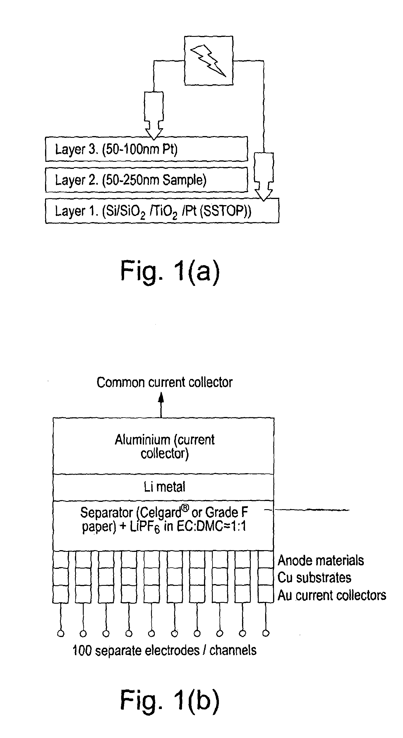
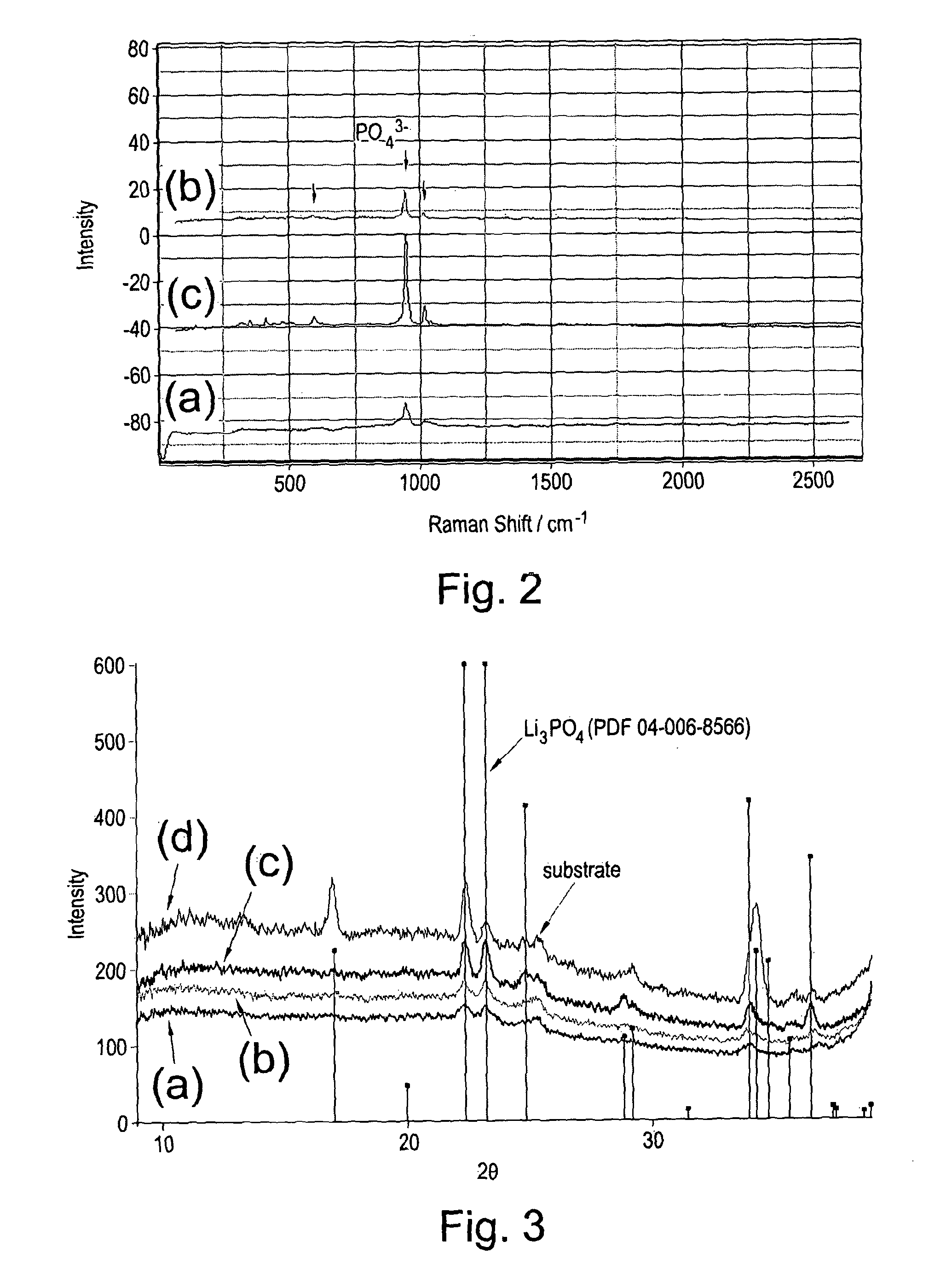
[0091]A series of uniform composition samples were prepared for characterisation and electrical measurements. The deposition of Li3PO4 films was achieved by co-depositing Li, P, and O in the appropriate atomic ratios on Si and Si / SiO2 / TiO2 / Pt (SSTOP) substrates. The evidence for the formation of the phosphate is the observation of the expected Raman bands in the as deposited sample at approximately 950 cm−1 and the observation of corresponding X-ray powder patterns in the samples after annealing in an oxygen gas atmosphere (FIGS. 2 and 3). The ionic conductivities of a series of Li3PO4 samples were measured as a function of annealing temperature. The results of impedance and DC measurements are shown in Table 1.

[0092]

TABLE 1The electrical properties of Li3PO4 thin film samples measuredusing impedance spectroscopy and DC current decay curves at constantvoltage. (N.b., the RAC values correspond to the low frequencyZ′ a...

example 2

Deposition and Characterisation of Mixtures of Lithium Ortho- and Pyro-Phosphate (Li3PO4 and Li4P2O7)

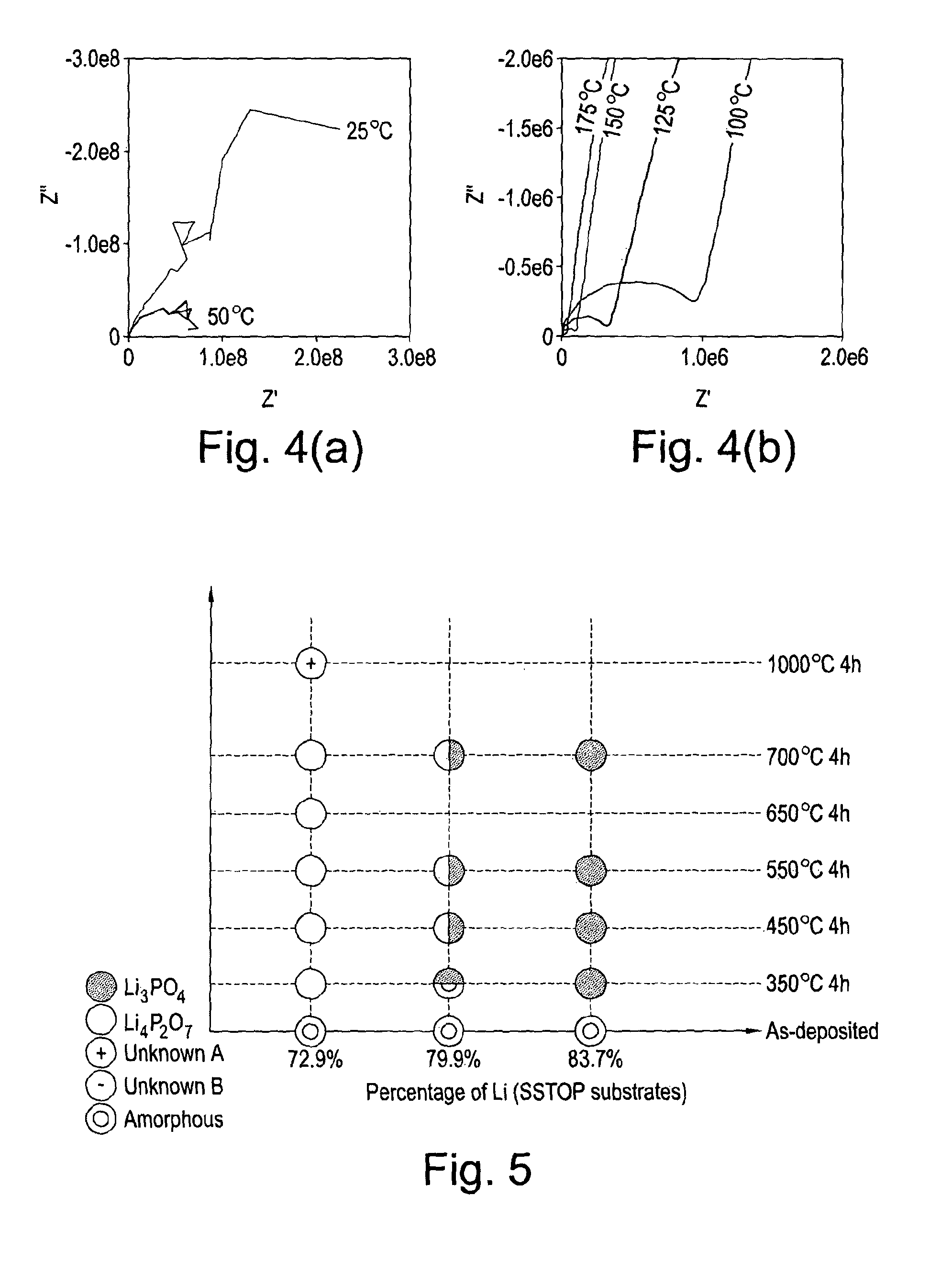
[0099]In a manner similar to Example 1, the deposition of mixed phases (i.e., lithium ortho-phosphate (Li3PO4) and lithium pyro-phosphate (Li4P2O7) films) or pure lithium pyro-phosphate was achieved by co-depositing uniform layers of Li, P, and O in the appropriate atomic ratios on Si and Si / SiO2 / TiO2 / Pt (SSTOP) substrates. In FIG. 5 the results of XRD analysis of a series of LIPOx samples with Li contents ranging from 72.9 to 83.7 at. % Li are shown as a function of annealing temperature (Note: The compositions were measured vs. NIST 610 and thus have a systematic error that over estimates the Li content relative to P by approximately 5 at. %). It is apparent from this data that the nature of the material synthesised depends, among other things, primarily on the atomic composition of the film. The composition of each specific point on the sample is determined by the relative deposit...

example 3

Deposition and Characterisation of Mixtures of Lithium Ortho- and Gyro-Phosphate (Li3PO4 and Li4P2O7) as Gradients on a Single Substrate

[0100]The co-deposition of a gradient of Li metal in the presence of atomic P and O produces a compositional variation across the sample substrate. This method of physical vapour deposition is termed Wedge Growth PVD (or HT-PVD). As shown above (Example 1), conclusive evidence for the formation of the target lithium phosphates is the observation of the expected Raman spectrum for the materials. According to the wedge growth effect, the composition of a specific point on the sample is determined by the relative deposition rates of the component elements at that point, which in this example is determined by the wedge gradient imposed on the Li source. A gradient composition sample was prepared in which a constant flux of oxygen and phosphorus was present during the deposition of a gradient in the Li content. The Raman spectra obtained as a function of...


PUM

PropertyMeasurementUnit
atomic numberaaaaaaaaaa
temperatureaaaaaaaaaa

Abstract

A vapor deposition process for the preparation of a chemical compound, wherein the process comprises providing each component element of the chemical compound as a vapor, and co-depositing the component element vapors on a common substrate, wherein: the vapor of at least one component element is provided using a cracking source; the vapor of at least one other component element is provided using a plasma source; and at least one further component element vapor is provided; wherein the component elements react on the substrate to form the chemical compound.

Description

[0001]This application is a national stage application under 35 U.S.C. §371 of PCT International Application No. PCT / GB2012 / 051741, filed Jul. 20, 2012, which claims the benefit of Great Britain Patent Application No. 1112600.0, filed Jul. 21, 2011, which is hereby incorporated by reference in its entirety.[0002]The present invention provides a vapour deposition process for the preparation of a chemical compound. The present invention also provides a process for the manufacture of a battery utilising the vapour deposition process of the present invention.[0003]Thin film materials have become important in a wide range of applications, such as in thin film semiconductors, thin film batteries, thin film photovoltaic cells and the like. As a consequence, there is a desire to be able to provide an ever-increasing range of materials as thin films. In particular, there is a desire to be able to discover, optimise, and manufacture chemical compounds for use in thin film applications more ea...

Claims


Application Information

Patent Timeline
Patent Type & Authority Patents(United States)
IPC IPC(8): C23C14/34C23C14/24C30B23/06C30B23/08C01B25/30C23C16/513H01M4/58H01M4/04H01M4/136H01M4/1397C23C14/08C01B21/20C01B25/45H01M10/0525
CPCC01B25/30C23C14/24C30B23/066C30B23/08H01M4/5825H01M4/0428H01M4/136H01M4/1397C23C14/08H01M4/0421C01B21/203C01B25/45H01M10/0525Y02E60/122Y02E60/10Y02P70/50C23C14/06C23C14/548H01M10/38
Inventor HAYDEN, BRIAN ELLIOTTLEE, CHRISTOPHER EDWARDSMITH, DUNCAN CLIFFORD ALANBEAL, MARK STEPHENLU, XIAOJUANYADA, CHIHIRO
Owner ILIKA TECH LTD
Why Eureka
Try Eureka