
Container for use in stereolithographic systems

a stereolithographic system and container technology, applied in the direction of manufacturing enclosures, applying layer means, manufacturing tools, etc., can solve the problems of low chemical and mechanical stability of the pdms layer, not being freely scalable in size, and requiring complicated optical manufacturing processes

Active Publication Date: 2022-03-29
DENTSPLY SIRONA INC
View PDF23 Cites 0 Cited by
  • Summary
  • Abstract
  • Description
  • Claims
  • Application Information

AI Technical Summary

Benefits of technology

The goal of this invention is to provide an arrangement that solves the problems of existing solutions by making it easy to supply an inhibitor with a solid base.

Problems solved by technology

The biggest drawback is the low chemical and mechanical stability of the PDMS layer.
All of the known solutions have the disadvantage that they are not freely scalable in size and typically require complicated optical manufacturing processes, for example to form channel structures.
Self-supporting PDMS arrangements have the disadvantage that they are flexible; consequently, buckling during the manufacturing process cannot be prevented.
On the other hand, rigid materials such as glass have mechanical and optical advantages, but provide no capability for the diffusion of a gaseous inhibitor, so that there is no formation of an inhibition layer.
The cost of Teflon AF is very high, however, in particular in plate form.
The use as a (self-supporting) film fails because the film sags.

Method used


Image

  • Container for use in stereolithographic systems
  • Container for use in stereolithographic systems
  • Container for use in stereolithographic systems

Examples


Embodiment Construction

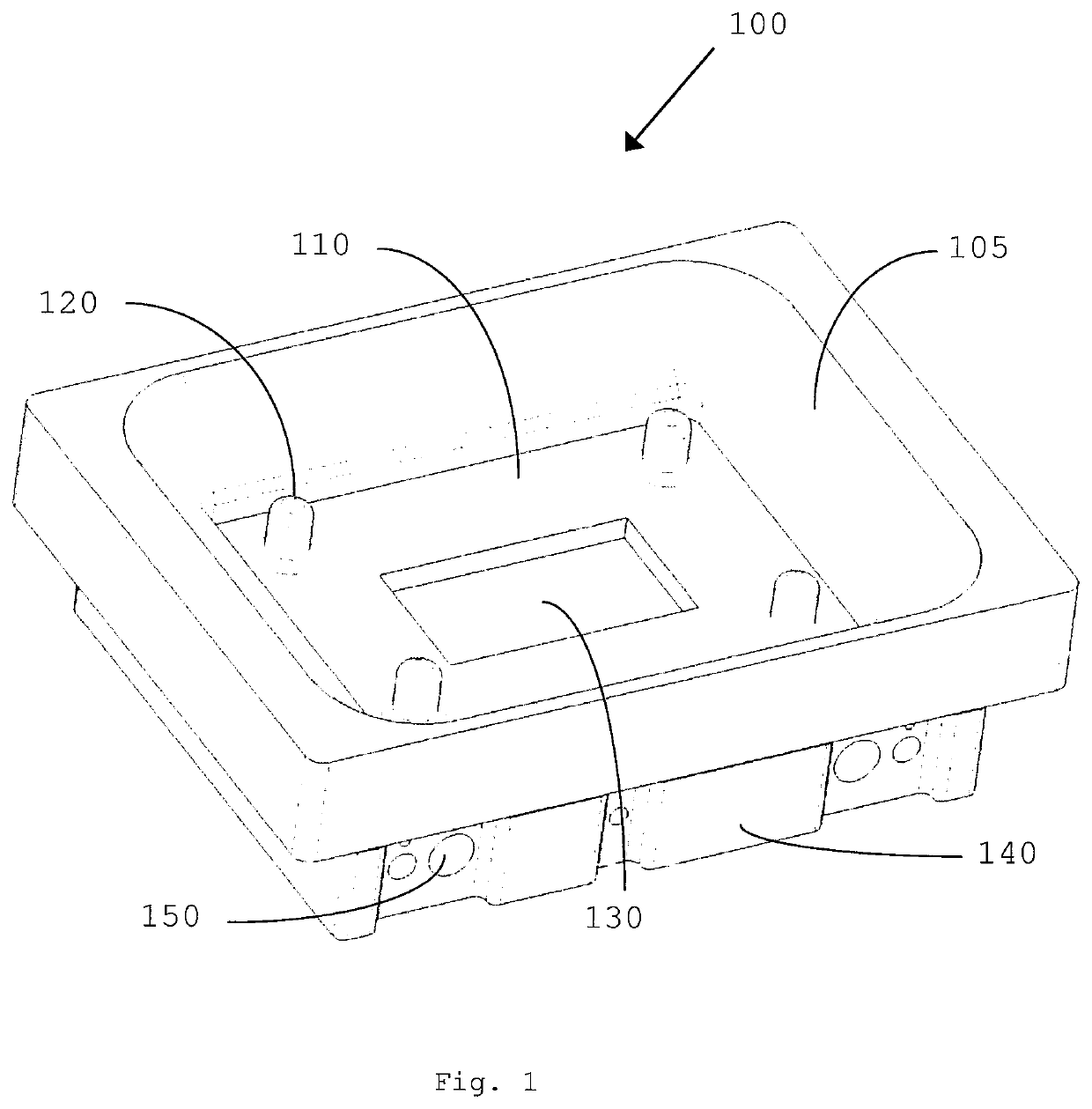
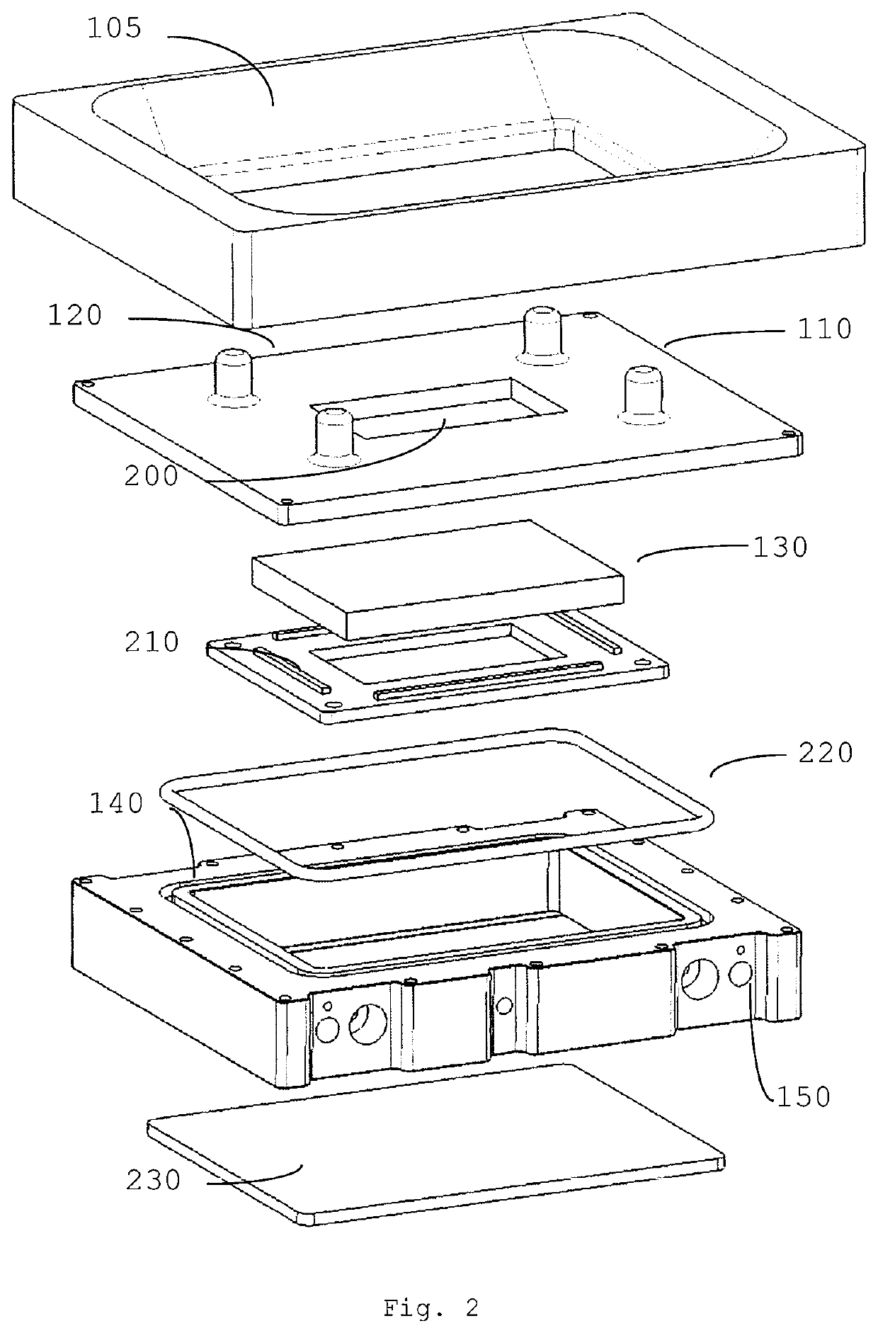
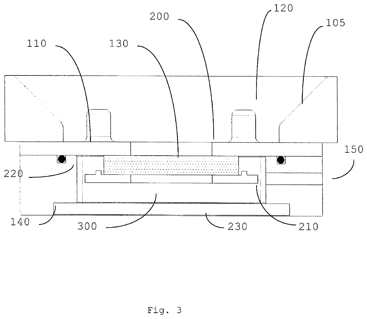
[0048]FIG. 1 shows a tank 100 according to the invention for use in an overhead stereolithographic system. In this design, the wall 105 and the outer region 110 of the bottom of the tank, above which the reference layer is not located, can be made of a conventional material. Four covers 120 for mounting screws are located in this region. The region in which the reference layer is located above the bottom of the tank during operation is in the middle of the tank. In the conventionally manufactured bottom of the tank 110, there is a recess, below which there is a block 130 that preferably consists of an aerogel or of one of the above-described combinations of different layers including at least one aerogel. This block is preferably approximately 3 mm thick, with a side length of several centimeters. It is held by the substructure 140 of the tank, which can also be made of a conventional material. The substructure is bolted to the upper part 110 of the tank, as a result of which the ae...


PUM

PropertyMeasurementUnit
pore sizeaaaaaaaaaa
pore sizeaaaaaaaaaa
printing speedsaaaaaaaaaa

Abstract

The invention relates to a container for holding a photosensitive liquid for use in a stereolithographic system in which a reference layer is exposed to radiation for the layer-by-layer or continuous creation of workpieces. At least one element of the container which is directly adjacent to the reference layer consists of at least one material which is at least partially transparent to the radiation and at least some of which has structures and / or pores which can receive and discharge, preferably also store, an inhibitor and / or an inhibitor mixture. Therefore, the element is not just able to supply the inhibitor but to a significant extent consists of the inhibitor itself, as a result of which the supplied flow is equalized or homogenized. Rapid or even continuous 3D printing is thus made possible in a cost-effective manner.

Description

TECHNICAL FIELD[0001]The invention relates to a part of a stereolithographic system.[0002]In a stereolithographic system, a three-dimensional body is produced from a photosensitive substance by layer-by-layer or continuous stacking of layers or layer information.[0003]In stereolithography according to the overhead method, the first layer of the workpiece, i.e. prior to the first step of the actual generative process, is transferred to a carrier (e.g. attached by means of a polymerization process). The carrier is able to perform a movement relative to the focal plane or reference layer. A next process step ensures that new material of the photosensitive substance can flow into the reference layer under the most recently produced layer or polymerization front. This can be achieved by a single lifting movement, for example, or a combination of lifting movements. The replenished photosensitive substance can then again cure under exposure to light.[0004]In stereolithography according to ...

Claims


Application Information

Patent Timeline
Patent Type & Authority Patents(United States)
IPC IPC(8): B29C64/245B29C64/255B29C64/124B29K105/00B33Y30/00
CPCB29C64/245B29C64/124B29C64/255B29K2105/0058B33Y30/00B33Y10/00B29C64/209B29C64/321G03F7/0037
Inventor SCHMIDT, CHRISTIAN
Owner DENTSPLY SIRONA INC
Learn More