Emission lifetime measuring method and apparatus for measuring a mean lifetime of electronically excited states

a technology of electronic excited states and measuring methods, applied in the direction of instruments, fluorescence/phosphorescence, analysis by material excitation, etc., can solve the problems of requiring considerable computation time, complex mathematical procedures based on iterative minimization, and requiring arbitrarily complex shapes, etc., to achieve significant facilitation of the analysis of the response function section, greatly reduce the complexity of signal processing, and increase the effect of speed

Active Publication Date: 2019-04-30
MAX PLANCK GESELLSCHAFT ZUR FOERDERUNG DER WISSENSCHAFTEN EV
View PDF4 Cites 0 Cited by
  • Summary
  • Abstract
  • Description
  • Claims
  • Application Information

AI Technical Summary

Benefits of technology

[0015]The at least one excitation light pulse, in particular the steady-state excitation section thereof, has a duration which is longer than the emission lifetime of the sample. This is in contrast to conventional techniques wherein the lifetime is measured after an excitation of a non-equilibrium state of the sample with an ultra-short excitation pulse being substantially shorter than the lifetime to be measured. Thus, as a first main advantage of the invention, creating and controlling the at least one excitation light pulse is essentially facilitated compared with conventional techniques. A second important advantage is a greater intensity and energy of the excitation pulse, leading to an enhanced signal-to-noise characteristic of the detected emission.
[0016]Furthermore, according to the invention, the mean lifetime of the electronically excited states is calculated on the basis of a temporal position of the linear response function section relative to a reference time of the at least one excitation light pulse, e. g. begin of steady-state excitation section, and / or on the basis of the slope of the linear response function section. In particular, the mean lifetime of the electronically excited states is calculated on the basis of a temporal position of the linear response function section elicited by the least one excitation light pulse relative to the corresponding response of a reference signal representing the excitation pulse directly or the response of material with known emission decay characteristics. The linear response function section is characterized by a slope and an intercept on the temporal axis evaluated in a manner permitting a comparison with the reference response. The inventors have found, that the mean lifetime can be directly derived from the linear response function section of the detector response function. Thus, as a second main advantage of the invention, analysing the response function section is substantially facilitated. Contrary to the conventional techniques, the detector signal is analysed by linear algebraic procedures, in particular without need for a deconvolution, resulting in greatly reduced signal processing complexity. This improves in particular FLIM applications of the invention, as emission lifetime images can be measured with increased speed and / or without loss of spatial resolution in the case of an imaging system.
[0017]According to a second general aspect of the invention, the above objective is solved by an emission lifetime measuring apparatus, in particular for measuring the mean lifetime of electronically excited states of a sample, comprising an excitation source device being arranged for illuminating the sample with at least one excitation light pulse, in particular at least two excitation light pulses, a detector device being arranged for time-resolved detecting the emission response from the sample and creating the temporal detector response function, and an analysing device being arranged calculating the mean lifetime of the electronically excited states on the basis of the detector response function. According to the invention, the excitation source device is adapted for shaping the at least one excitation light pulse such that the sample achieves the equilibrium excited steady-state including the linearly increasing or constant number of the electronically excited states and the detector response function has the linear response function section with a constant slope. Furthermore, the analysing device is adapted for calculating the mean lifetime of the electronically excited states on the basis of a temporal position of the linear response function section relative to a reference time of the at least one excitation light pulse and / or on the basis of the slope and intercept of the linear response function section. Preferably, the method of the first aspect of the invention is conducted with the apparatus of the second aspect of the invention.
[0018]Advantageously, the basic concept of the invention is to replace the very narrow pulses currently used in excited state decay estimation (e.g. of fluorescence lifetime) by at least one excitation pulse encompassing a constant gradient or constant flat (plateau) section longer (e.g. 8-fold longer) than the longest excited state lifetime of the sample. The output signal of the detector device, which may include a single detector element (e. g. APDs, PMTs, hybrids, SPADs), and array of detector elements or a camera, preferably a gated intensified camera, is measured instantaneously or in integrated manner up to different, appropriately selected time points (at least 2 determinations are required). During the excited steady-state, the detector response function demonstrates a universally linear temporal increase, from which an intensity-weighted lifetime for arbitrarily complex heterogeneous solutions or microscope specimens can be instantly estimated without deconvolution, in particular without iterative techniques. The fact that very short (even sub-ns) lifetimes can be determined with long excitation light pulses is not intuitively obvious and accounts for the absence of this approach in the conventional techniques. Compared with conventional techniques, the inventive technique has advantages in terms of sensitivity of emission response detection, photon efficiency, speed of signal processing, and reduced complexity of algorithms in signal processing. Furthermore, the invention is unique in providing the mean lifetime directly, regardless of sample complexity. Furthermore, it also incorporates the capability for measurement of the individual decays without equipment modification.
[0019]According to a first embodiment of the invention, the steady-state excitation section of the at least one excitation light pulse is a linear ramp section (or: linear excitation ramp section). With a sequence of excitation light pulses, the excitation has a saw tooth intensity shape whereby the decaying limb need not be linear. The steady-state excitation section of the excitation pulse(s) has a linear increase of the pulse intensity, wherein the length the ramp is selected such that the equilibrium excited steady-state of the sample is achieved in a corresponding detection time window. During the linear ramp section, the number of electronically excited states in the sample is increasing linearly in time. Accordingly, the detector response function comprises the time-dependent emission response from the sample. The linear response function section follows the linear ramp section with a temporal delay defined by the intercept on the temporal axis defined for 0 net signal intensity or by the temporal displacement of suitably normalized signals, both cases corresponding to the mean emission lifetime to be measured.
[0020]Preferably, the mean lifetime τ of the electronically excited states is calculated with the first embodiment of the invention using the equation τ=t−rf(t) / srf(t) or an equation derived therefrom, wherein t is the time position after the initiation of the pulse, rf(t) is the emission response at the considered time position, and srf(t) is the slope of the linear response function section at time t. In the linear region, srf[t] is constant. Preferably, the mean lifetime τ is calculated with the analysing device of the lifetime measuring apparatus.

Problems solved by technology

The experimental difficulty in conventional time-domain measurements, in particular FLIM, featuring excitation light pulses of narrow but finite width results from the fact that the detector response function is given by the convolution of the excitation light pulse with the exponential emissive decay function, and is thus arbitrarily complex in shape.
Furthermore, data analysis of the detector response function for deriving the decay time requires deconvolution of the response and / or restriction of the data set to a final segment of the decay.
In both cases, complex mathematical procedures based on iterative minimization are involved.
These require considerable computation time, even with current computers, extending to minutes in the event that more than a single decay component is present.
This limitation applies to all current FLIM or single channel lifetime techniques.

Method used


Image

  • Emission lifetime measuring method and apparatus for measuring a mean lifetime of electronically excited states
  • Emission lifetime measuring method and apparatus for measuring a mean lifetime of electronically excited states
  • Emission lifetime measuring method and apparatus for measuring a mean lifetime of electronically excited states

Examples


first embodiment

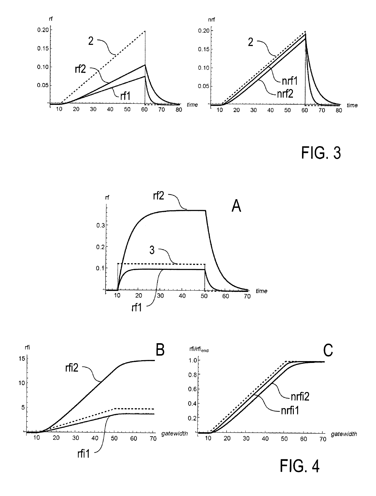
[0057]According to FIG. 3, the dotted line represents the ramp section 2 of an excitation light pulse according to the invention. In the equilibrium excited steady-state of sample 1, the time-dependent emission response rf of the sample has a linear response function section (linearly increasing ramp shape) as well. Drawn lines rf1 and rf2 in FIG. 3A illustrate two examples of samples having a fluorescence lifetime of 2 ns (rf1) and 5 ns (rf2). Due to the longer fluorescence lifetime, the linear response function section of emission response rf2 has a steeper slope and a higher final value than the linear response function section of emission response rf1. Emission responses rf1 and rf2 are displaced relative to the excitation light pulse and relative to each other. The displacement, which is further demonstrated with the normalized detector response function in FIG. 3B, is linearly dependent on the mean lifetime of the sample, being equal to the lifetime upon comparison with a refe...

second embodiment

[0069]According to FIG. 4A, the dotted line represents the pulse section 3 with constant intensity of an excitation light pulse according to the invention. The extended rectangular excitation light pulse 3 provides a rapid increase in excitation energy followed by a constant level which is maintained for an interval corresponding to several times the lifetime(s) being measured. The response function curves immediately after the initial rise and final fall of the excitation light pulse 3 are exponential and provide additional data for obtaining the lifetimes according to conventional techniques.

[0070]Drawn lines rf1 and rf2 in FIG. 4A illustrate two examples of samples having a fluorescence lifetime of 2 ns (rf1) and 5 ns (rf2). In the equilibrium excited steady-state of sample 1, the time-dependent emission response rf of the sample has a flat shape (FIG. 4A), while the time-integrated emission responses rfi1, rfi2 of the samples which are actually recorded n the experiment each hav...

third embodiment

[0082]Pulse shapes other than rectangular, i.e. with different shapes (finite rise times), can also be used in the invention (third embodiment). The response curves and the analytical mathematical expressions for the corresponding rfi curves have been computed for numerous examples. In all cases, the same behaviour of the rfi signals is observed after attainment of the steady state, i.e. as in FIG. 4B for the rectangular pulse.

[0083]With a practical measurement according to the second embodiment (using the pulse section 3 with constant intensity), the integration is started before the excitation light pulse 3, then keep incrementing the gate width (always starting from the same point) until the excitation is completed (end of the excitation light pulse). With 100-200 points (frames) one defines the integrated response function in detail. In the case of the rectangular excitation light pulse 3, the immediate “dynamic response” (population kinetics of the excited state) takes place on...


PUM

PropertyMeasurementUnit
time resolutionaaaaaaaaaa

Abstract

An emission lifetime measuring method, in particular for measuring a mean lifetime of electronically excited states of a sample, comprises the steps of illuminating the sample with at least one excitation light pulse, time-resolved detecting an emission response from the sample and creating a temporal detector response function, and calculating the mean lifetime of the electronically excited states on the basis of the detector response function, wherein the at least one excitation light pulse is shaped such that the sample achieves an equilibrium excited steady-state including a linearly increasing or constant number of the electronically excited states, the detector response function has a linear response function section with a constant slope, and the mean lifetime (τ) of the electronically excited states is calculated on the basis of at least one of a time position of the linear response function section relative to a reference time of the at least one excitation light pulse and the slope of the linear response function section. Furthermore, an emission lifetime measuring apparatus (100) is described.

Description

CROSS REFERENCE TO RELATED APPLICATIONS[0001]This application is the U.S. National Phase Application of PCT / EP2016 / 000055, filed Jan. 13, 2016, the contents of which is incorporated herein by reference in its entirety for all purposes.FIELD OF THE INVENTION[0002]The present invention relates to an emission lifetime measuring method and apparatus, in particular for measuring a mean lifetime, e. g. a fluorescence or phosphorescence lifetime, or an equivalent feature characterizing the temporal decay of electronically excited states of a sample. Applications of the invention are available in the fields of investigating samples, e. g. in biology, medicine, material sciences or environmental technologies.TECHNICAL BACKGROUND[0003]The estimation of emission lifetimes (excited state lifetimes), e. g. based on fluorescence or phosphorescence emission is an essential technique in basic and applied science. Lifetime (tau, τ) determinations provide sensitive measures of binding and other molec...

Claims


Application Information

Patent Timeline
Patent Type & Authority Patents(United States)
IPC IPC(8): G01N21/64
CPCG01N21/6408G01N21/6486G01N21/6458G01N2021/641
Inventor JOVIN, THOMAS M.COOK, NATHAN P.
Owner MAX PLANCK GESELLSCHAFT ZUR FOERDERUNG DER WISSENSCHAFTEN EV
Why Eureka
Try Eureka