Angled lighting integrated into a ceiling t-bar

Active Publication Date: 2018-09-13
JLC TECH IP LLC
View PDF0 Cites 3 Cited by
  • Summary
  • Abstract
  • Description
  • Claims
  • Application Information

AI Technical Summary

Benefits of technology

[0007]With this invention, a T-bar is provided which includes a lighting source within a housing which is asymmetrical and angled so that light emanating therefrom is not straight downward, but rather shines at an angle to vertical and horizontal, and is thus “lateral” in orientation. In this way, light can be shown upon a wall or onto some other space other than space directly downward below the T-bar. Positioning of light beneath the ceiling can thus be somewhat independent of the location of the T-bars within the ceiling, rather than req

Problems solved by technology

Such known prior art LED lights within T-bars have, to this point, been limited to general lighting shining downward from the T-bar.
However, such spotlights in many instances take up more space within a room then i

Method used


Image

  • Angled lighting integrated into a ceiling t-bar
  • Angled lighting integrated into a ceiling t-bar
  • Angled lighting integrated into a ceiling t-bar

Examples


Example

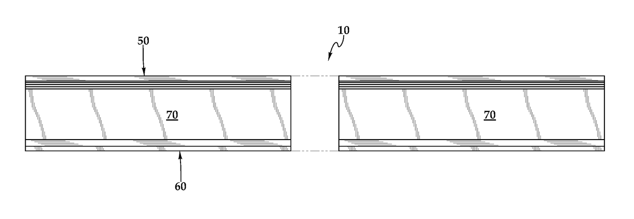
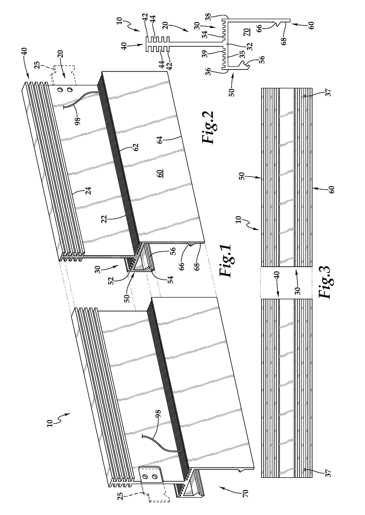
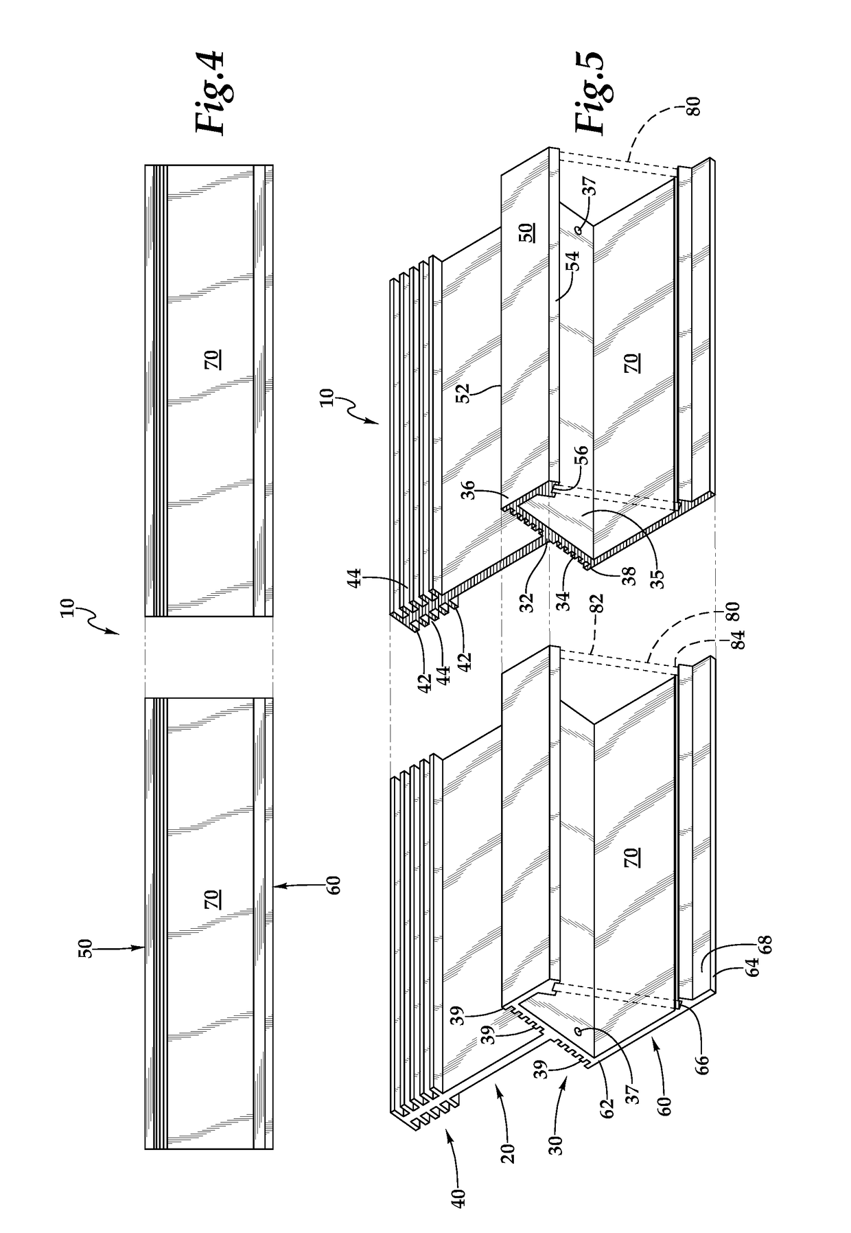
[0038]Referring to the drawings, wherein like reference numerals represent like parts throughout the various drawing figures, reference numeral 10 is directed to an angled lighting T-bar (FIGS. 1, 2, 5, 10 and 11) which provides the dual function of holding up ceiling tiles C within a dropped ceiling of an interior space, and also acting as a support for a light source 90 so that light L can shine from the T-bar 10 in a manner angled away from vertical and horizontal, such as to shine light upon a wall W and a sign S, picture P, door D or other item on the wall W, or to otherwise beneficially direct light in a manner other than generally downward from the T-bar 10.

[0039]In essence, and with particular reference to FIGS. 1, 2, 5 and 9-11, basic details of the T-bar 10 are described, according to an exemplary embodiment. The T-bar 10 includes a spine 20 extending up from a rest shelf 30, with the rest shelf 30 supporting edges of ceiling tiles C thereon, and with the spine 20 supporti...


PUM


Abstract

A housing is located at least partially beneath a rest shelf of a T-bar or other support for ceiling tiles. A spine extends up from the rest shelf. The housing includes an opening with a centerline which extends at least partially laterally. A light source such as an LED within a recess of the housing shines out of the opening along the centerline in an at least partially lateral direction. A diffuser is preferably provided spanning this opening. The housing preferably includes a front wall opposite a rear wall, with the rear wall larger than the front wall and with the opening in the housing extending between lower portions of the rear wall and lower portions of the front wall. Heat transfer fins on an upper surface of the rest shelf and upper end of the spine are preferably provided to assist in heat dissipation.

Description

CROSS-REFERENCE TO RELATED APPLICATIONS[0001]This application claims benefit under Title 35, United States Code § 119(e) of U.S. Provisional Application No. 62 / 502,948 filed on May 8, 2017. Each of U.S. Pat. Nos. 8,177,385 and 9,879,850 and U.S. patent application Ser. No. 15 / 863,276 are incorporated herein by reference in their entirety. This application is a continuation-in-part of U.S. patent application Ser. No. 15 / 863,276 filed on Jan. 5, 2018, which is a continuation of U.S. patent application Ser. No. 13 / 634,219 filed on Sep. 11, 2012 and issued as U.S. Pat. No. 9,879,850 on Jan. 30, 2018, which is a continuation and claims benefit of the earlier filing dates associated with International Application No. PCT / US2011 / 000455 filed on Mar. 10, 2011, which designates the United States and other countries; and is a continuation of U.S. patent application Ser. No. 12 / 661,252 filed on Mar. 11, 2010 and issued as U.S. Pat. No. 8,177,385 on May 15, 2012, which was claimed for priority ...

Claims


Application Information

Patent Timeline
IPC IPC(8): F21V29/76F21V23/02F21S4/28F21V33/00E04B9/00E04B9/06F24F3/056F21S2/00F21S8/02F21S8/04F21V29/503F21V29/74F21Y105/10F21Y115/10
CPCF21S8/02F21S8/043F21V29/503F21S8/026E04B9/006E04B9/067F21S2/005F21S8/04F21V33/006F21V33/0088F24F3/056F21V23/023F21V23/026F21Y2105/10F21Y2115/10F21S4/28F21V29/767F21V29/74F21V29/763E04B9/064F21V21/048F21V29/76F21Y2103/10
Inventor PORCIATTI, SILVIO
Owner JLC TECH IP LLC
Why Eureka
Try Eureka