Vehicle headlamp

a headlamp and headlamp technology, applied in the field of headlamps, can solve the problems of reducing weight, reducing cost, and downsizing, and achieve the effects of reducing the number of components, and improving long-distance visibility

Active Publication Date: 2013-12-31
ICHIKOH IND LTD
View PDF40 Cites 4 Cited by
  • Summary
  • Abstract
  • Description
  • Claims
  • Application Information

AI Technical Summary

Benefits of technology

[0015]the first reflecting surface is a reflecting surface made of a free curved face for light-distributing and controlling a reflection image of the light emitting chip, so that the reflection image of the light emitting chip does not run out of the oblique cutoff line and the horizontal cutoff line and a part of the reflection image of the light emitting chip is substantially in contact with the oblique cutoff line and the horizontal cutoff line;
[0016]the second reflecting surface is a reflecting surface made of a free curved face for light-distributing and controlling a reflecting image of the light emitting chip, so that the reflection image of the light emitting chip does not run out of the oblique cutoff line and the horizontal cutoff line and a part of the reflection image of the light emitting chip is substantially in contact with the oblique cutoff line and the horizontal cutoff line and so that density of a reflection image group of the light emitting chip becomes lower than density of a reflection image group of the light emitting chip according to the first reflecting surface and the reflection image group of the light emitting chip contains the reflection image group of the light emitting chip according to the first reflecting surface; and
[0058]Moreover, the vehicle headlamp according to the first aspect of the present invention is made of a reflector and a semiconductor-type light source, so that the number of components is reduced in comparison with the conventional vehicle headlamp, and downsizing, weight reduction, or cost reduction can be achieved accordingly. Furthermore, the vehicle headlamp according to the first aspect of the present invention is characterized in that a relationship in the number of components between light sources and optical elements is obtained as that of one semiconductor light source to one optical element made of a reflector (1:1). As a result, the vehicle headlamp according to the first aspect of the present invention becomes capable of eliminating an error concerning a combination of variations at the optical element side and improving precision of assembling the reflector at the optical element, in combination with the conventional vehicle headlamp in which a relationship between the numbers of constituent light sources and optical elements is one constituent light source to three constituent optical elements, i.e., a reflector, a shade, and a projecting lens (1:3).
[0059]In addition, the vehicle headlamp according to the second aspect of the present invention becomes capable of reliably achieving both light-distributing and controlling of a light distribution pattern, optimal for vehicle use, and downsizing of a lamp unit, by means for solving the problem described previously.
[0060]Further, the vehicle headlamp according to the third aspect of the present invention is characterized in that a reflecting surface and a semiconductor-type light source are disposed so that an upside unit, a light emitting face of the light emitting chip being oriented upward in the vertical-axis direction and a downside unit, a light emitting face of the light emitting chip is oriented downward in the vertical-axis direction are established in a point-symmetrical state. As a result, even if a reflector is downsized, luminous intensity of a light distribution pattern is sufficiently obtained, thus ensuring that the vehicle headlamp according to the third aspect of the present invention becomes capable of more reliably achieving both light-distributing and controlling of a light distribution pattern, which is optimal for vehicle use, and downsizing of a lamp unit.

Problems solved by technology

However, the conventional vehicle headlamp is provided with a light source, a reflector, a shade, and a projecting lens, so that a large number of components are required, and there is a problem concerning downsizing, weight reduction, and cost reduction accordingly.
Thus, in the conventional vehicle headlamp, an error concerning a combination of variations in the three constituent optical elements, i.e., the reflector, the shade and the projecting lens occurs, and there is a problem concerning precision of assembling the three constituent optical elements, i.e., the reflector, the shade, and the projecting lens.

Method used


Image

  • Vehicle headlamp
  • Vehicle headlamp
  • Vehicle headlamp

Examples


Embodiment Construction

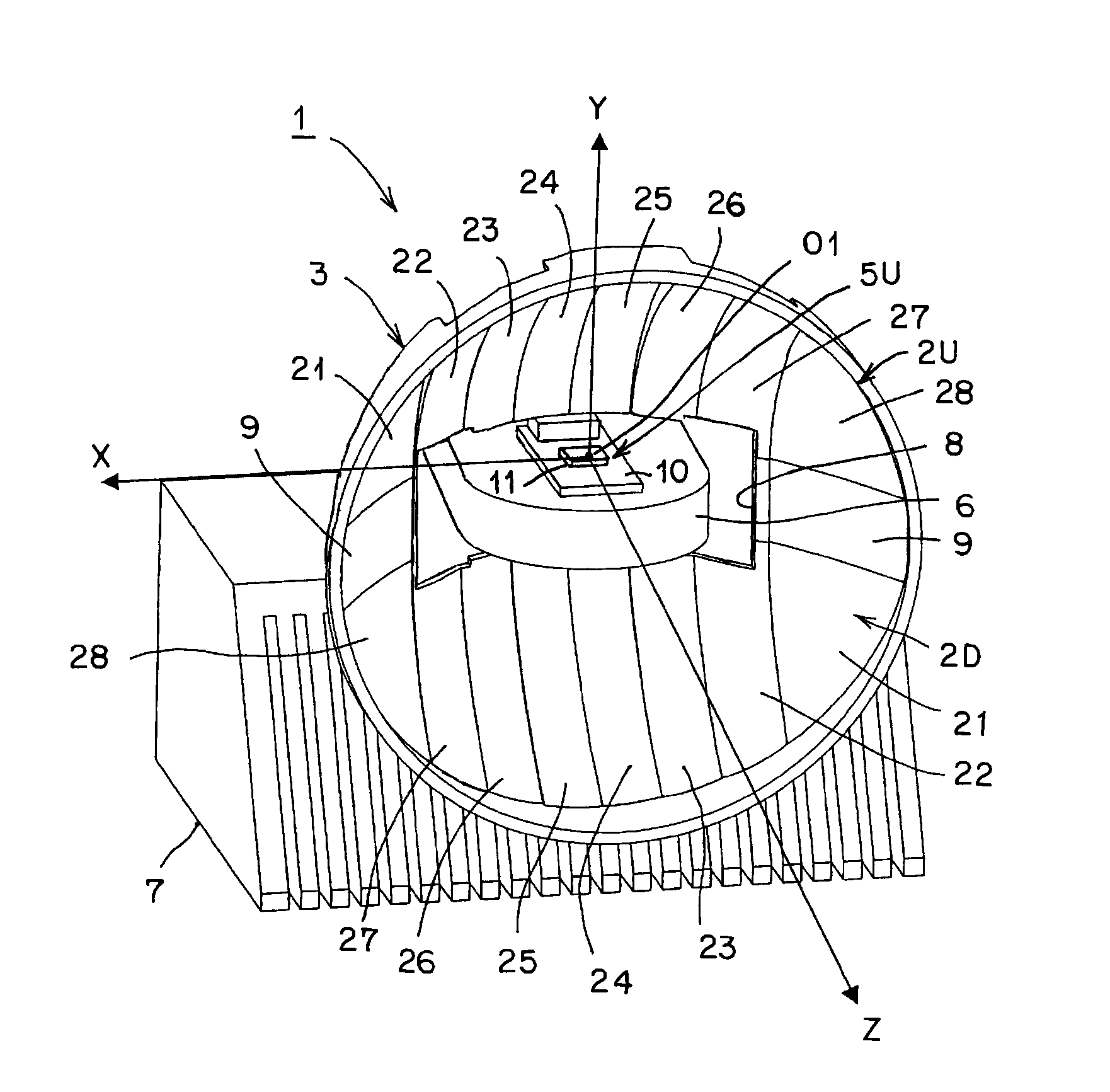
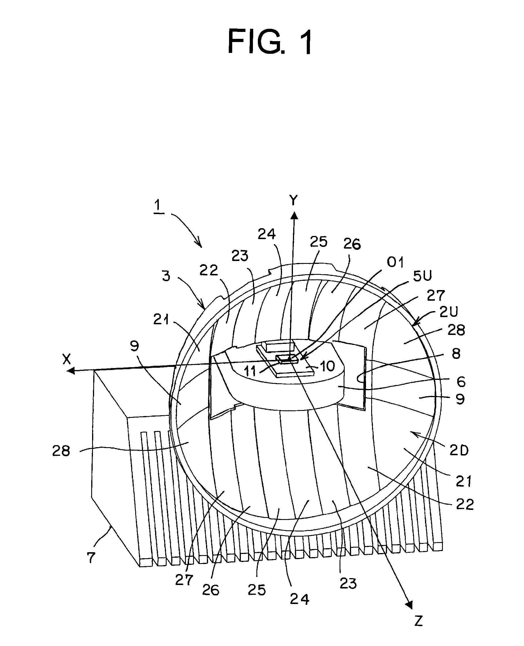
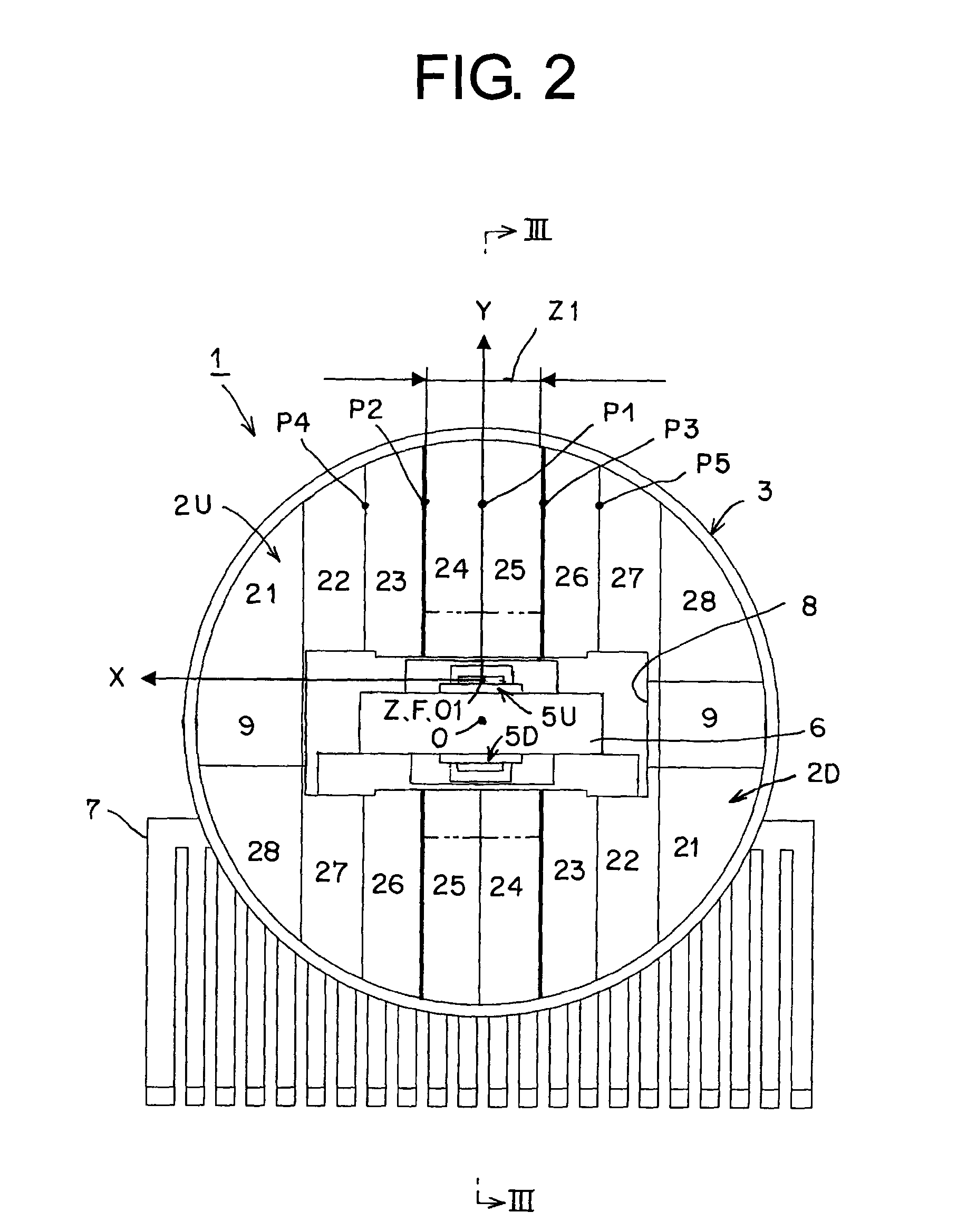
[0073]Hereinafter, an embodiment of a vehicle headlamp according to the present invention will be described in detail, referring to the drawings. The present invention is not limited by the embodiment. In the drawings, the letter symbol “VU-VD” designates a vertical line of the top and bottom of a screen; and the letter symbol “HL-HR” designates a horizontal line of the left and right of the screen. FIGS. 10 and 11 are explanatory views, each of which shows a group of reflection images of a light emitting chip on a screen, obtained by computer simulation. In the specification and claims, the terms “top”, “bottom, “front”, “rear”, “left”, and “right” designate “top”, “bottom”, “front”, “rear”, “left”, and “right” of a vehicle when the vehicle headlamp according to the present invention is mounted on a vehicle (automobile).

[0074]Hereinafter, a configuration of the vehicle headlamp in the embodiment will be described. In the drawings, reference numeral 1 denotes the vehicle headlamp (a...


PUM


Abstract

A vehicle headlamp is provided with: a reflector having reflecting surfaces made of a parabola-based free curved face; and semiconductor-type light sources having a light emitting chip shaped like a planar rectangle. The reflecting surfaces 2U, 2D are made up of: a first reflecting surface forming a high luminous intensity zone; a second reflecting surface forming a middle luminous intensity zone; and a third reflecting surface forming a low luminous intensity zone. As a result, the vehicle headlamp allows downsizing, weight reduction, and cost reduction. In addition, precision of assembling optical elements can be improved.

Description

CROSS-REFERENCE TO RELATED APPLICATIONS[0001]This application claims priority of Japanese Patent Application No. 2008-280071 filed on Oct. 30, 2008. The contents of this application are incorporated herein by reference in their entirety.BACKGROUND OF THE INVENTION[0002]1. Field of the Invention[0003]The present invention relates to a vehicle headlamp for illuminating a light distribution pattern, for example a light distribution pattern for low beam (light distribution pattern for passing), toward a forward direction of a vehicle, the light distribution pattern having an oblique cutoff line at a cruising lane side and having a horizontal cutoff line at an opposite lane side, with an elbow point serving as a boundary.[0004]2. Description of the Related Art[0005]Vehicle headlamps of this type are conventionally known (Japanese Laid-open Patent Application No. 2007-109493 and Japanese Laid-open Patent Application No. 2007-172882, for example). Hereinafter, a conventional vehicle headla...

Claims


Application Information

Patent Timeline
Patent Type & Authority Patents(United States)
IPC IPC(8): B60Q1/00
CPCF21S48/328F21S48/1159F21S48/1163F21S48/1358F21Y2101/02F21V29/004F21V29/763F21V29/225F21S48/1317F21Y2115/10F21S41/155F21S41/334F21S41/151F21S45/48F21S41/148
Inventor OOKUBO, YASUHIRO
Owner ICHIKOH IND LTD
Why Eureka
Try Eureka