
Device for locking workpieces on machine tools

a technology for locking workpieces and machine tools, which is applied in the direction of metal-working holders, positioning apparatuses, supports, etc., can solve the problems of deformation of workpieces, compromise the quality of machining, and the risk of workpieces getting out of toleran

Active Publication Date: 2020-05-12
HYDROBLOCK
View PDF11 Cites 0 Cited by
  • Summary
  • Abstract
  • Description
  • Claims
  • Application Information

AI Technical Summary

Benefits of technology

[0014]The main aim of the present invention is to provide a device for locking workpieces on machine tools which allows stably locking a workpiece to be machined on a machine tool without charging it from the tensional point of view and without deforming it.
[0015]A further object of the present invention is to provide a device for locking workpieces on machine tools which, overhang being equal, can exert higher locking forces on the workpiece being machined, and which, locking force being equal, can operate with greater overhangs.
[0016]Another object of the present invention is to provide a device for locking workpieces on machine tools which allows to overcome the mentioned drawbacks of the prior art within the ambit of a simple, rational, easy and effective to use as well as affordable solution.

Problems solved by technology

Still in the automotive sector, moreover, the use is increasingly more frequent of particularly lightweight materials such as aluminum which, nevertheless, during the machining on the machine tool, are not able to ensure the same resistance as materials such as cast iron and steel.
It is therefore necessary that the locking clamp of the workpiece, besides exercising a very high force, rests on the workpiece at predetermined points, with great precision and in a repeatable way each time a new workpiece to be machined is mounted on the machine tool; on the contrary, in fact, the high force exerted by the clamp may cause the deformation of the workpieces, which compromises the quality of the machining and the risk of getting out-of-tolerance workpieces.
In this regard the fact should also be underlined that the high forces that the clamp exerts on the workpiece lead the rod to bend and / or twist, which not only risks damaging the oil hydraulic cylinder but changes the contact area between the clamp and the workpiece, thus increasing the risk of performing faulty machining operations.
Clearly, the pressure / force curve has an increasing pattern while the pressure / length curve has a decreasing pattern and the fixing systems of known type must work in situations of compromise which are not always entirely satisfactory.

Method used


Image

  • Device for locking workpieces on machine tools
  • Device for locking workpieces on machine tools
  • Device for locking workpieces on machine tools

Examples


Embodiment Construction

[0014]The main aim of the present invention is to provide a device for locking workpieces on machine tools which allows stably locking a workpiece to be machined on a machine tool without charging it from the tensional point of view and without deforming it.

[0015]A further object of the present invention is to provide a device for locking workpieces on machine tools which, overhang being equal, can exert higher locking forces on the workpiece being machined, and which, locking force being equal, can operate with greater overhangs.

[0016]Another object of the present invention is to provide a device for locking workpieces on machine tools which allows to overcome the mentioned drawbacks of the prior art within the ambit of a simple, rational, easy and effective to use as well as affordable solution.

[0017]The above mentioned objects are achieved by the present device for locking workpieces on machine tools having the characteristics of claim 1.

BRIEF DESCRIPTION OF THE DRAWINGS

[0018]Oth...


PUM


Abstract

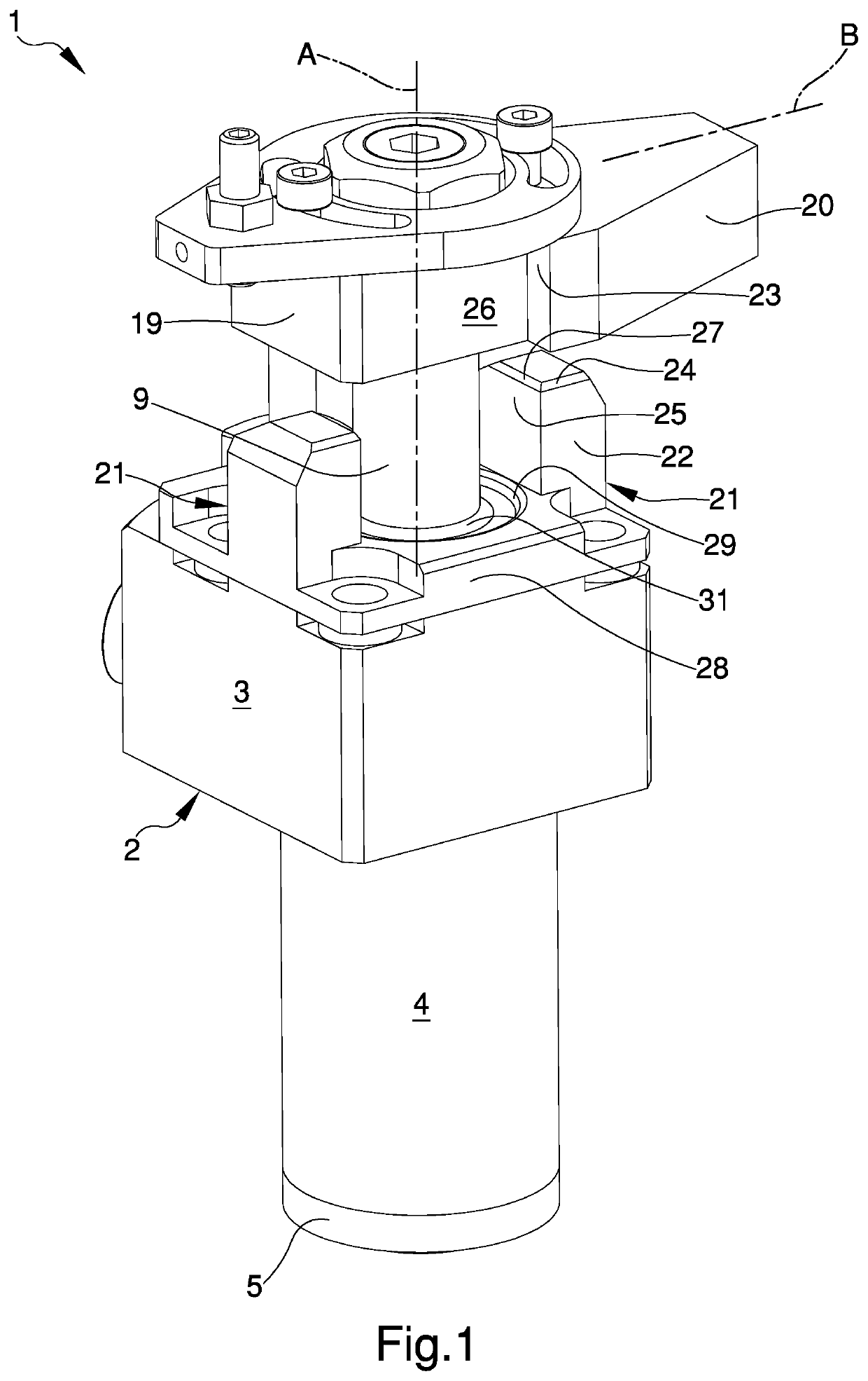
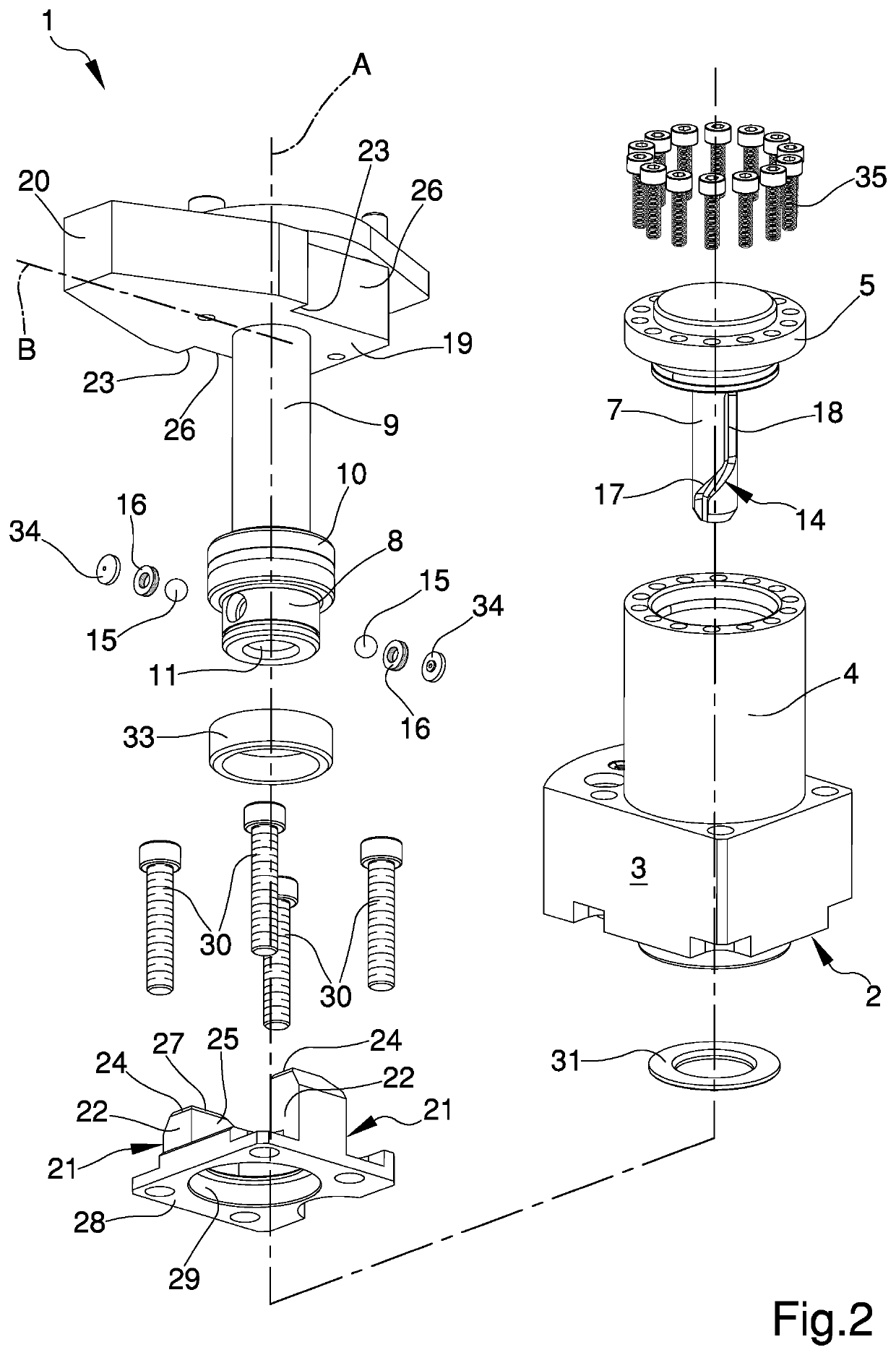
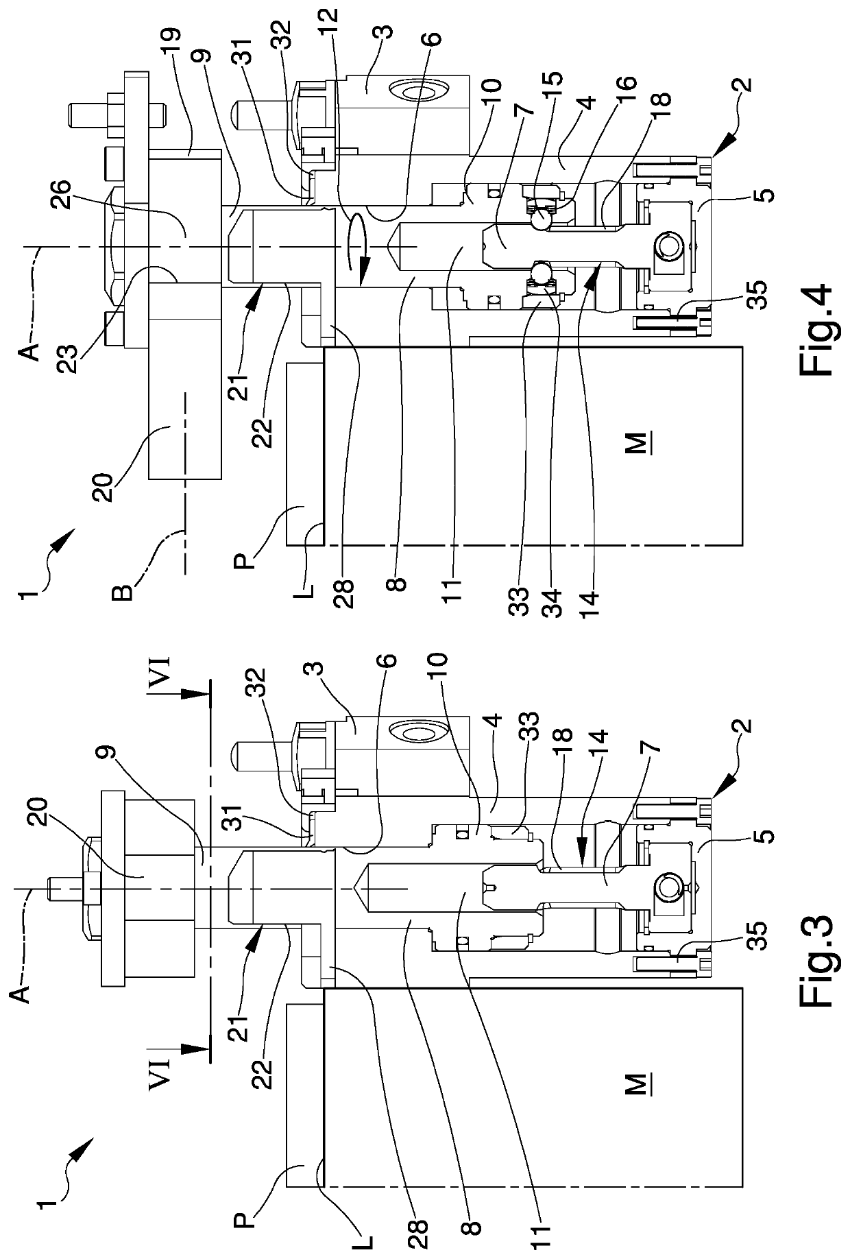
The device (1) for locking workpieces on machine tools comprises:—a base body (2) fixable to a machine tool (M) and provided with an oil hydraulic cylinder (3, 4, 5); 5—a rod (8, 9) partly inserted in the oil hydraulic cylinder (3, 4, 5) slidably;—roto-translation means (14, 15, 16) designed to divide the motion of the rod (8, 9) into:—a first stretch (12) of roto-translation; and—a second stretch (13) of translation; 10—a clamp element (19, 20) associated with the rod (8, 9) and movable between:—a home configuration;—an intermediate configuration; and—an operating configuration; 15—at least a prismatic guiding body (21) associated with the base body (2) and prismatically couplable with the clamp element (19, 20) during the shifting of the rod (8, 9) along the second stretch (13).

Description

TECHNICAL FIELD[0001]The present invention relates to a device for locking workpieces on machine tools.BACKGROUND ART[0002]Suitable fixing systems are usually used for locking workpieces to be machined on a machine tool.[0003]A particular type of fixing systems consists of a clamp which, by means of an oil hydraulic drive, is movable both in a rotating manner about an axis of rotation and in a sliding manner along the same axis of rotation.[0004]The clamp is mounted overhanging on the rod of an oil hydraulic actuator partly inserted in an oil hydraulic cylinder.[0005]Between the rod and the oil hydraulic cylinder there are roto-translation means, i.e. special constraint means that allow the rod, and therefore the clamp mounted on it, roto-translating.[0006]Such fixing systems must be able to exert huge locking forces on the piece being machined.[0007]This need is particularly felt, e.g., in the automotive sector, in which the continuous need to optimize production cycles has led to ...

Claims


Application Information

Patent Timeline
Patent Type & Authority Patents(United States)
IPC IPC(8): B23Q3/00B25B5/06B25B5/08B25B5/16
CPCB25B5/087B25B5/062B25B5/166
Inventor ZANNI, DAVIDE
Owner HYDROBLOCK
Learn More