Hybrid vehicle

a hybrid vehicle and electric power storage technology, applied in the field of hybrid vehicles, can solve the problems of low travel load, low possibility, and high achieve the effects of reducing the state of charge facilitating engine start and reducing the amount of energy of electric power storage devices

Active Publication Date: 2020-05-19
TOYOTA JIDOSHA KK
View PDF6 Cites 0 Cited by
  • Summary
  • Abstract
  • Description
  • Claims
  • Application Information

AI Technical Summary

Benefits of technology

[0005]The disclosure provides a hybrid vehicle that suppresses an amount of energy of an electric power storage device capable of being used in a travel section in a CD mode from becoming smaller than expected in the case where the vehicle travels in accordance with a travel plan in which the CD mode or a CS mode is assigned to each of the travel sections of a travel plan route to a destination.
[0007]In this hybrid vehicle of the disclosure, when the specified condition including such a condition that the destination has been set is not satisfied, the first control is executed to control the engine and the motor such that the hybrid vehicle travels by switching between the CD mode and the CS mode. When the specified condition is satisfied, the second control is executed to control the engine and the motor such that the hybrid vehicle travels in accordance with the travel plan in which the CD mode or the CS mode is assigned to each of the travel sections of the travel plan route to the destination. In addition, in the CS mode in the second control, the engine and the motor are controlled such that the state of charge of the electric power storage device becomes higher than that in the CS mode in the first control. In this way, compared to the case where the same control as that in the CS mode in the first control is executed in the CS mode in the second control, the state of charge of the electric power storage device can be made high in the travel section in the CS mode in the second control. As a result, it is possible to suppress an amount of energy of the electric power storage device, which can be consumed in the following travel section in CS mode in the second control, from becoming smaller than expected. Here, the CD mode is a mode in which the state of charge of the electric power storage device is reduced. The CS mode is a mode in which the state of charge of the electric power storage device is maintained within a management range including a control center.
[0008]In such a hybrid vehicle of the disclosure, the controller may be configured to set a start threshold of the engine to be lower in the CS mode in the second control than in the CS mode in the first control. In this way, in the CS mode in the second control, a start of the engine is facilitated in comparison with the CS mode in the first control. Thus, the state of charge of the electric power storage device can be made high.
[0009]In addition, in the hybrid vehicle of the disclosure, the controller may be configured to set a stop threshold of the engine to be lower in the CS mode in the second control than in the CS mode in the first control. In this way, in the CS mode in the second control, a stop of the engine is impeded in comparison with the CS mode in the first control. Thus, the state of charge of the electric power storage device can be made high.
[0010]Furthermore, in the hybrid vehicle of the disclosure, in the CS mode in the second control, the controller may execute at least one of increasing a target charged / discharged amount of the electric power storage device to a charged side, increasing allowable charge electric power of the electric power storage device, and reducing allowable discharge electric power of the electric power storage device in comparison with those in the CS mode in the first control. In this way, in the CS mode in the second control, the state of charge of the electric power storage device can be made higher than that in the CS mode in the first control by increasing the target charged-discharged amount of the electric power storage device to the charged side.

Problems solved by technology

In the case where the state of charge of the electric power storage device is made high in the travel section in the CS mode when the distance to the destination is short, there is a possibility that the high state of charge of the electric power storage device cannot sufficiently be consumed in the travel section in the CD mode to the destination.
When the current location is not on the controlled-access highway, it is considered that, compared to the controlled-access highway, a travel load is low and there is a low possibility that a larger amount of the energy of the electric power storage device than expected is consumed in the travel sections in the CS mode and the CD mode.
Accordingly, in the case where the state of charge of the electric power storage device is made high in the travel section in the CS mode, there is the possibility that the high state of charge of the electric power storage device cannot sufficiently be consumed in the travel section in the CD mode to the destination.
When the current location is in the congested section, it is considered that the travel load is low and there is the low possibility that the larger amount of the energy of the electric power storage device than expected is consumed in the travel sections in the CS mode and the CD mode.
Accordingly, in the case where the state of charge of the electric power storage device is made high in the travel section in the CS mode, there is the possibility that the high state of charge of the electric power storage device cannot sufficiently be consumed in the travel section in the CD mode to the destination.

Method used


Image

  • Hybrid vehicle
  • Hybrid vehicle
  • Hybrid vehicle

Examples


Embodiment Construction

[0023]Next, a mode for carrying out the disclosure will be described by using an embodiment.

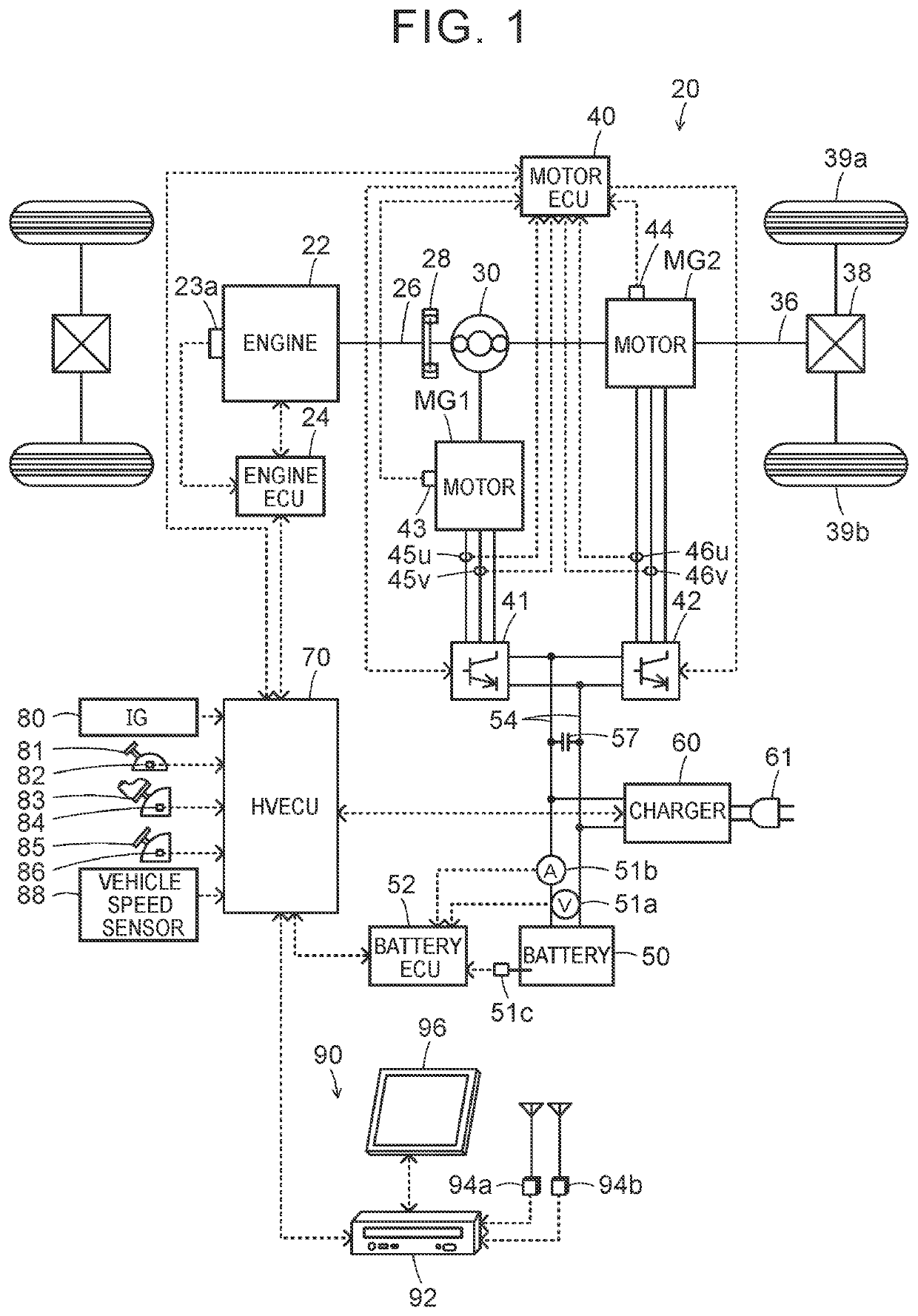
[0024]FIG. 1 is a configuration diagram that schematically shows a configuration of a hybrid vehicle 20 as an embodiment of the disclosure. As shown in FIG. 1, the hybrid vehicle 20 of the embodiment includes an engine 22, a planetary gear 30, motors MG1 MG2, inverters 41, 42, a battery 50 as an electric power storage device, a charger 60, a navigation system 90, and a hybrid electronic control unit (hereinafter referred to as a “HVECU”) 70.

[0025]The engine 22 is configured as an internal combustion engine that uses fuel such as gasoline or diesel fuel to output power, and is connected to a carrier of the planetary gear 30 via a damper 28. An operation of this engine 22 is controlled by an engine electronic control unit (hereinafter referred to as an “engine ECU”) 24.

[0026]Although not shown, the engine ECU 24 is configured as a microprocessor having a CPU as a central component and includes,...


PUM


Abstract

A hybrid vehicle includes a controller. First control is control of an engine and a motor such that the hybrid vehicle travels by switching between a charge depleting mode and a charge sustaining mode. Second control is control of the engine and the motor such that the hybrid vehicle travels in accordance with a travel plan in which the charge depleting mode or the charge sustaining mode is assigned to each travel section of a travel plan route to a destination. The controller controls the engine and the motor such that a state of charge of an electric power storage device becomes higher in the charge sustaining mode in the second control than in the charge sustaining mode in the first control.

Description

CROSS-REFERENCE TO RELATED APPLICATIONS[0001]This application claims priority to Japanese Patent Application No. 2018-023023 filed on Feb. 13, 2018, which is incorporated herein by reference in its entirety including the specification, drawings and abstract.BACKGROUND1. Technical Field[0002]The disclosure relates to a hybrid vehicle and, in particular, to a hybrid vehicle that includes an engine, a motor, and an electric power storage device.2. Description of Related Art[0003]Conventionally, as a hybrid vehicle of this type that includes an engine, a motor, and a battery that stores electric power from the motor and supplies electric power to the motor, a hybrid vehicle in which a charge depleting (CD) mode or a charge sustaining (CS) mode is assigned to each travel section of a travel plan route to a destination on the basis of a travel load so as to create a plan and in which the engine and the motor are controlled to realize travel in accordance with the plan has been proposed (f...

Claims


Application Information

Patent Timeline
Patent Type & Authority Patents(United States)
IPC IPC(8): B60W10/08B60W50/08B60W10/26B60W30/182B60K6/365B60W20/00B60K6/28B60K1/02B60K6/445B60W20/13B60K6/46
CPCB60K6/28B60W50/082B60W10/08B60K1/02B60K6/445B60W20/13B60W10/26B60W30/182B60K6/365B60K6/46B60Y2200/92B60W2510/244B60W2300/18B60L2240/54B60L2260/28B60W2710/244B60W20/12B60W20/20B60K6/48B60K2006/4825B60W2556/50B60W2554/406B60W10/06Y02T10/62Y02T10/70Y02T90/14Y02T10/7072
Inventor OGAWA, YUKI
Owner TOYOTA JIDOSHA KK
Why Eureka
Try Eureka