Movable detector and methods for inspecting elongated tube-like objects in equipment

a technology of movable detectors and equipment, applied in the direction of instruments, material magnetic variables, material analysis, etc., can solve the problems of coke dust mixed in the air, cost and time, and operator safety and health problems,

Active Publication Date: 2020-05-19
RAYONG ENG & PLANT SERVICE CO LTD
View PDF7 Cites 0 Cited by
  • Summary
  • Abstract
  • Description
  • Claims
  • Application Information

AI Technical Summary

Benefits of technology

[0036]According to an aspect of the invention a movable detector and a method for inspecting the equipment in which equipment can be inspected at various locations along the coils or tubes during operation. Detection comprises moving the detector along the coils / tubes. The detector and method allow detection of an equipment state indication. In an embodiment carburization is measured using a sensor that is held at a predetermined distance from the tube during detection. The distance is maintained between surface of elongated tube-like object which is to be inspected and a sensor while moving the detector along the tube or coils. Maintaining the distance constant during detection continuous measurement at similar circumstances, e.g. also when the surface of equipment is bent, convex or rough and also gives precise information quickly without cost and time of scaffolding installation. Operators do not have to work in a confined space and in the area with a lot of coke dust mixed in the air. This could eliminate safety and health problems of operators in case of coils investigation in the furnaces of olefins production.

Problems solved by technology

Operators have to work at the high level, in confined space and there can be a lot of coke dust mixed in the air.
Therefore, it may cause problems of safety and health to operators.
Moreover, installing scaffolding results in costs and takes time.
Further time is needed for work preparation and it will take time to check the results of the measured values.
One disadvantage of such scanners is that the collar is sized to fit around the circumference of the pipe.
This is inconvenient in terms of time and moneywise.
Moreover, it is impossible or inconvenient to obtain measurements from bended, convex pipes or pipes with an uneven surface.
The apparatuses and methods in the prior art suffer from a problem caused by irregularities on the surface of the elongated tube-like object, such as bent, convex, etc.
These irregularities cause errors in the measurement and create difficulties for interpreting the measured data.
However the body-to-sensor-frame connection does not fully fix the position of the sensor frame to the body as the body-to-sensor-frame connection is arranged to allow at least one degree of freedom of the sensor frame and thereby also the sensor, with respect to the body.

Method used


Image

  • Movable detector and methods for inspecting elongated tube-like objects in equipment
  • Movable detector and methods for inspecting elongated tube-like objects in equipment
  • Movable detector and methods for inspecting elongated tube-like objects in equipment

Examples


first embodiment

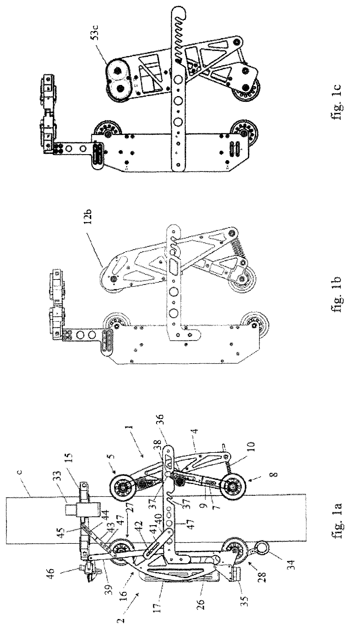
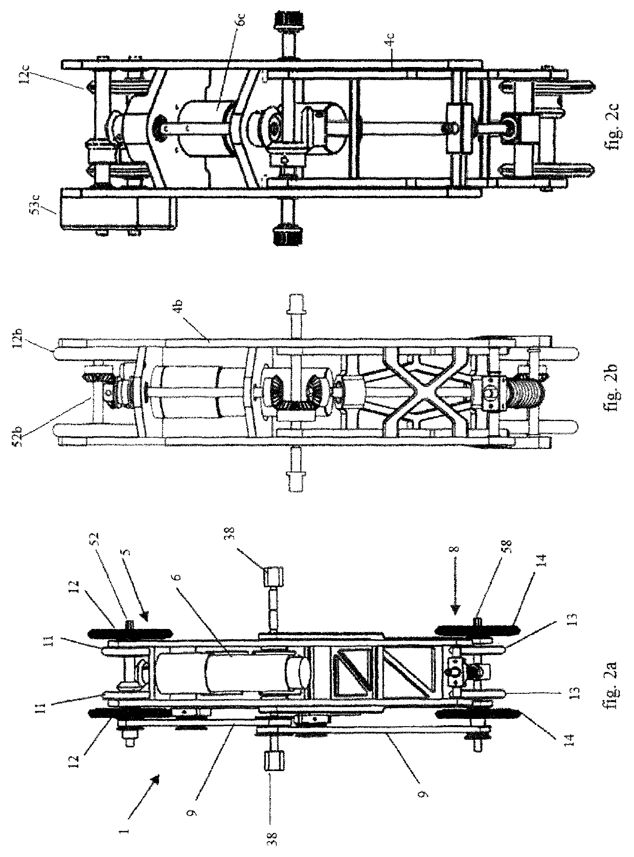
[0063]FIGS. 1-3 show the driving part 1 according to three respective side views. The first embodiment comprises:

[0064]a first wheel frame 4 onto which front wheels 5 are mounted;

[0065]a motor 6 for driving front wheels 5;

[0066]a second wheel frame 7, onto which rear wheels 8 are mounted;

[0067]a transmission belt 9 for transferring power from front wheels 5 to rear wheels 8; and

[0068]a wheel pusher 10 which is installed between a shaft 51 of rear wheels 8 and at the rear ea of the first wheel frame 4.

[0069]First wheel frame is an example of a frame that can be part of the first part or driving part 1 of the movable detector. The first wheel frame 4 allows mounting of front wheels 5, which are an example of a possible embodiment to allow the movable detector to move along the tube or coil C. In another embodiment a caterpillar can be used instead of wheels 5. Wheels 5 are mounted on the frame by a shaft 52. The wheels can comprise inflatable tires.

[0070]In an embodiment the front whe...

third embodiment

[0081]The third embodiment, FIGS. 1c and 2c, shows a transmission 53c, that can comprise gears to transmit the drive power onto the front wheels 11,12.

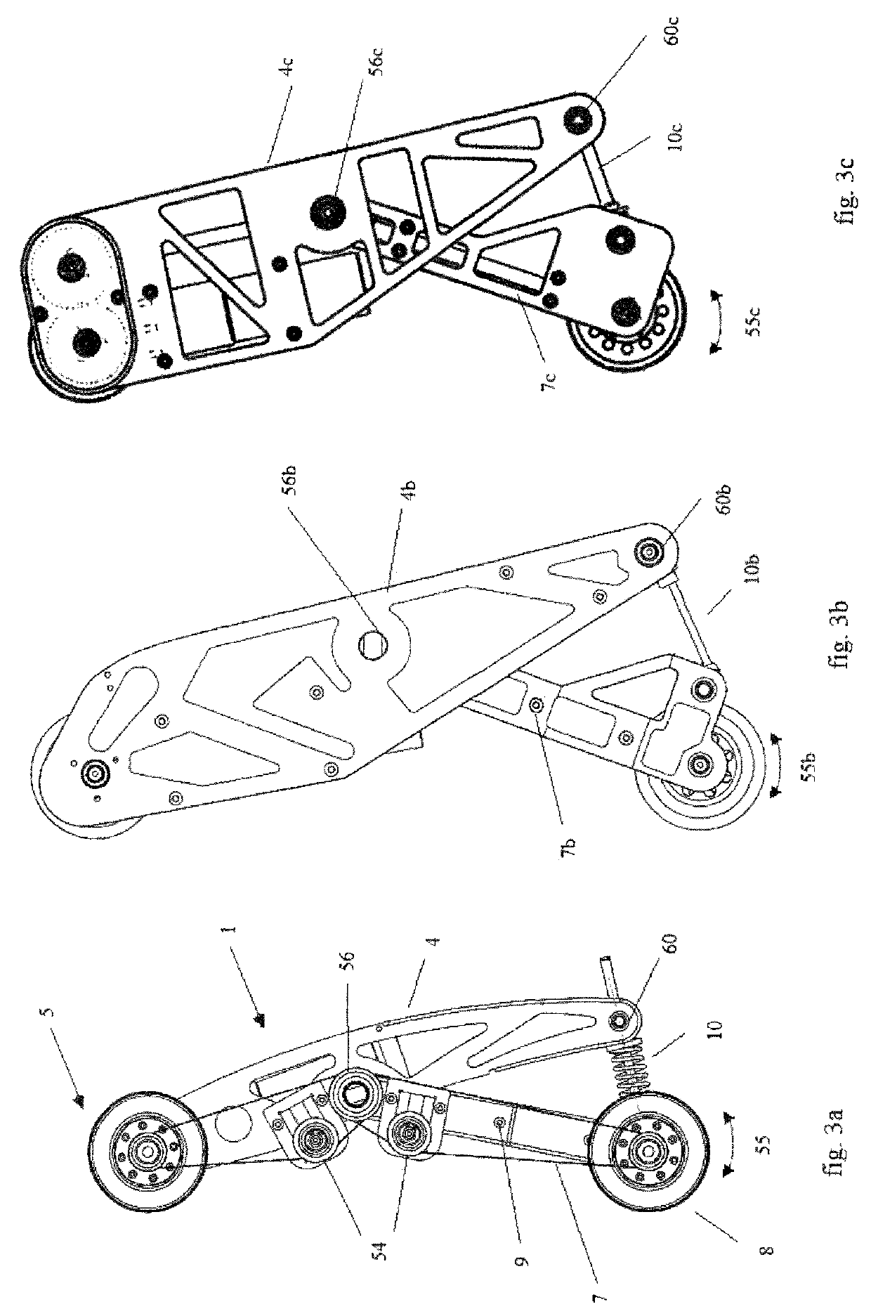
[0082]In the first embodiment a transmission belt 9 transfers power from front wheels 5 to rear wheels 8. The transmission belt 9 is tensioned using tension wheels 54. Clearly other embodiments for transferring power to the rear wheels 8 are possible. In an embodiment separate drives for the front and rear wheels are present. In an embodiment, instead of the transmission belt, a gear and a shaft are used for transferring power.

[0083]The rear wheels 8 are mounted on a shaft 51 that is connected to second wheel frame 7,7b,7c by bearings. Second wheel frame 7 can pivot according to arrow 55,55b,55c around an axis 56,56b,56c extending out / into the paper. A wheel pusher 10 connects the second wheel frame 7 to the first wheel frame 4 of the driving part 1. The wheel pusher 10 has bearings 60,60b,60c. The wheel pusher 10 pushes the second wh...

second embodiment

[0126]Other embodiments are shown in FIGS. 6b and 7b and 6c and 7c. The second embodiment shows four wheels 24b positioned centrally. This will allow positioning the sensor 20 / magnet 25 at a predetermined position for more different sized tubes / coils.

[0127]The third embodiment shows a sensor housing 19c that will be held at a predetermined position with respect to the coil / tubes by two arms 75c and springs 23c that are connected to the spring housing unit 21c.

[0128]Although some of the shown embodiments are directed at sensors for investigating contamination of the tubes / coils in the active equipment C by measuring the amount of carbon in coils / tubes, the invention is not limited to these kind of sensors.

[0129]In an embodiment a touch sensor 33, shown in FIGS. 1 and 8, is also mounted on the sensor frame 15. The touch sensor 33 is arranged to sense when the sensor frame 15 collides with an obstacle. The touch sensor 33 can arranged to control the movement of movable detector, such ...


PUM

PropertyMeasurementUnit
constant speedaaaaaaaaaa
distanceaaaaaaaaaa
restoring forceaaaaaaaaaa

Abstract

The invention relates to an apparatus and a method for inspecting an elongated tube-like object. The apparatus comprises a body (1, 2) for moving along the elongated tube-like object by clamping the object; and a sensor frame (15, 15b, 15c) supporting one or more sensors (20) for measuring a state indication property. One or more one or more body-to-sensor-frame connections (39, 40, 43, 72b, 72c) connect the sensor frame (15, 15b, 15c) to the body (1, 2), wherein the one or more body-to-sensor-frame connections (39, 40, 43, 72b, 72c) are arranged to allow an adjustable relative position between the sensor frame and the body, while the sensor frame can position itself with respect to the tube.

Description

CROSS-REFERENCE TO RELATED APPLICATIONS[0001]This application is a U.S. 371 National Stage entry of International Application Serial No. PCT / TH2017 / 000001 filed Jan. 16, 2017, which claims priority to Netherlands Application No. 2016102 filed Jan. 15, 2016. The contents of each of these applications are hereby incorporated herein by reference in their entirety as if set forth verbatim.TECHNICAL FIELD[0002]The invention relates to an apparatus or movable detector and the method for inspecting elongated tube-like objects in an equipment, such as tubes, pipes or coils. The invention also relates to program code for identification of a status property (e.g. expected remaining life time) of an elongated tube-like objects, such as pipes or coils.BACKGROUND ART[0003]Elongated tube-like objects, such as a pipe or a coil need to be investigated for leakage. Elongated tube-like objects, such as pipes, (radiant) coils or tubes, can require inspection on its outer surface. In some cases inspect...

Claims


Application Information

Patent Timeline
Patent Type & Authority Patents(United States)
IPC IPC(8): G01N27/82G01M3/40G01N21/952G01N21/95G01N29/265
CPCG01N29/265G01M3/40G01N27/82G01N21/952G01N21/9515G01N2291/262G01N2021/9518G01N2291/269G01N2291/02854
Inventor RUTTANASUPA, PAWINYANANONT, TERDSAKUMPAWANWONG, SANTIPAPPANDUM, PAISALSEANBUNSIRI, KANJANAS
Owner RAYONG ENG & PLANT SERVICE CO LTD
Why Eureka
Try Eureka