Communication system, relay device, and water warmer

a relay device and communication system technology, applied in transmission, electrical equipment, lighting and heating apparatus, etc., can solve the problems of inability to use the water warmer during software update of the water warmer, and time-consuming, so as to curb the deterioration of user convenience in software update.

Active Publication Date: 2020-06-02
NORITZ CORP
View PDF13 Cites 1 Cited by
  • Summary
  • Abstract
  • Description
  • Claims
  • Application Information

AI Technical Summary

Benefits of technology

[0007]The disclosure curbs deterioration of user convenience in software update of a water warmer using a communication system between a management device (server) and the water warmer through a relay device.
[0011]According to the communication system, the water warmer, and the relay device, software update of the water warmer which includes the reception of the update program through the communication cable is started on condition that a user's consent to the occurrence of an unavailable period of the water warmer due to the start of the software update is obtained. Therefore, it is possible to curb deterioration of user convenience due to the occurrence of an unexpected unavailable period through software update processing of the water warmer.
[0012]According to the disclosure, it is possible to curb deterioration of user convenience in software update of a water warmer using a communication system between a management device and a water warmer through a relay device.

Problems solved by technology

However, a time required for transmission of the update program from the communication adapter to the water warmer through 2-core communication is generally longer than a time required for downloading from a management device to the communication adapter.
Further, the water warmer cannot be used during software update of the water warmer.
Therefore, there is concern that user convenience will deteriorate due to start of the software update of the water warmer.

Method used


Image

  • Communication system, relay device, and water warmer
  • Communication system, relay device, and water warmer
  • Communication system, relay device, and water warmer

Examples


first embodiment

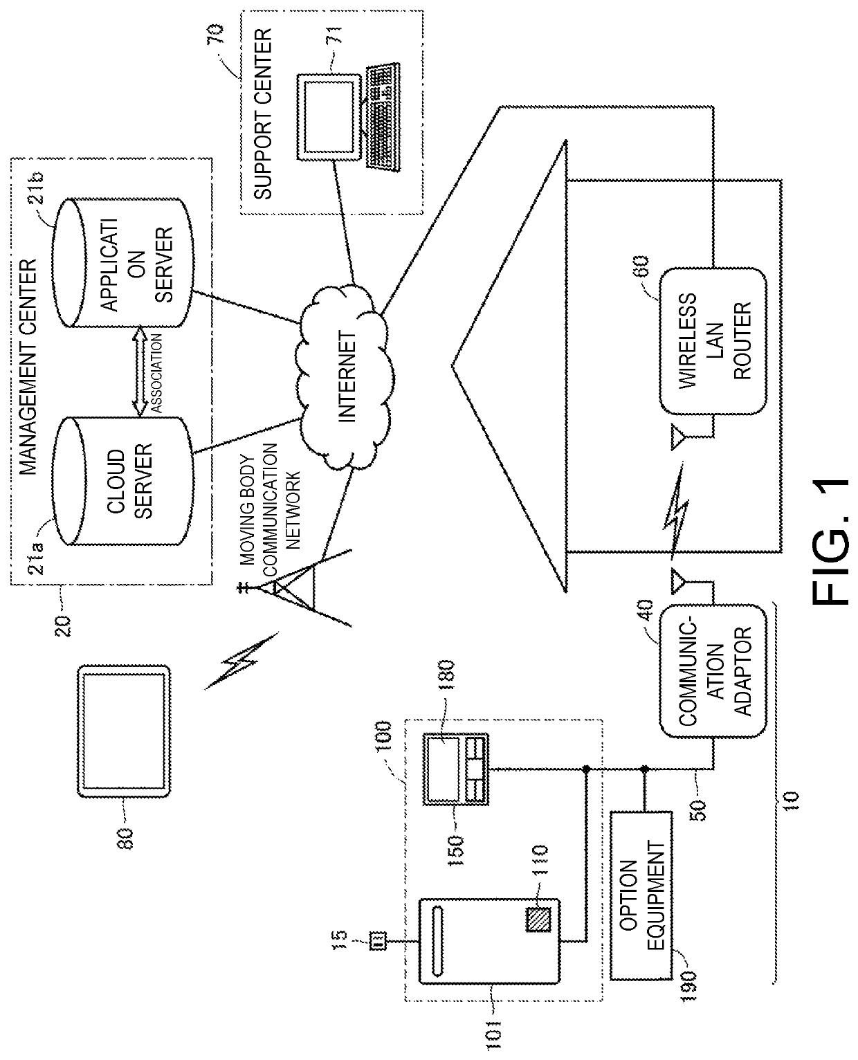
[0026]FIG. 1 is a block diagram showing a configuration example of a remote management system of a water warmer to which a communication system according to the present embodiment is applied.

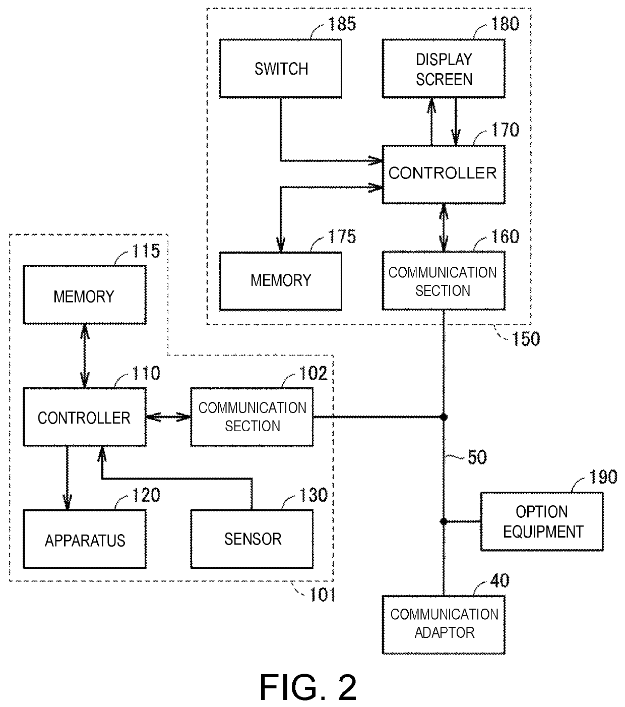
[0027]Referring to FIG. 1, a communication system 10 according to a first embodiment includes a water warmer 100 and a communication adaptor 40. The water warmer 100 includes a water heater 101 and a remote controller (hereinafter, also referred to simply as “a remote control”) 150 for inputting an operation instruction of the water heater 101. Note that the water warmer 100 may be configured to include a multi-hot water supply system, a bath water reheating device, a filtration device, or a hot water heating equipment instead of the water heater 101. The water heater 101 includes a controller 110. The controller 110 is representatively constituted by a microcomputer.

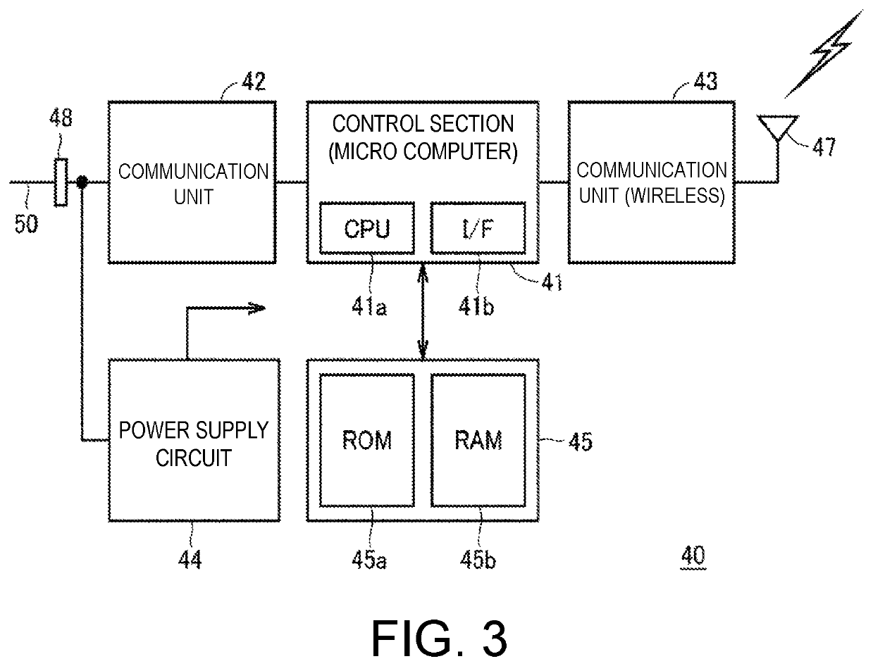
[0028]The communication adaptor 40 can be installed outdoors, for example, in the vicinity of the outer wall of a house or in a ga...

second embodiment

[0102]As described in the first embodiment, an update program for executing S / W update of the water warmer 100 is transmitted from the communication adaptor 40 to the water warmer 100 through communication using a 2-core communication cable 50 which takes a relatively long time. Therefore, retransmission of the entire update program during the stop of the update program from the communication adaptor 40 to the water warmer 100 results in a concern that a transmission time of the update program increases.

[0103]FIG. 9 is a flowchart illustrating transmission control of an update program from a communication adaptor 40 to a water warmer 100 in a communication system according to a second embodiment. The control processing of FIG. 9 is started up when communication C60 of FIG. 4 described in the first embodiment is started and is executed by a control section 41 of the communication adaptor 40.

[0104]Referring to FIG. 9, the control section 41 reads out program transmission condition inf...

third embodiment

[0115]In the communication systems described in the first and second embodiments, an update program used for S / W update of the water warmer 100 (the water heater 101 and the remote control 150) is stored in the memory 45 of the communication adaptor 40. Since a program of the communication adaptor 40 is stored in the memory 45 of the communication adaptor 40, it is necessary to efficiently use the capacity of the memory 45. In a third embodiment, the control of contents stored in a memory 45 of a communication adaptor 40 accompanying S / W update of a water warmer 100 will be described.

[0116]In FIGS. 10A, 10B, and 10C, conceptual diagrams illustrating software update in a communication system according to the third embodiment are shown.

[0117]In FIG. 10A, a state before S / W update is shown. In the communication adaptor 40, a program P1 stored in the memory 45 is being executed, a program P2 is being executed in a water heater 101, and a program P3 is being executed in a remote control ...


PUM


Abstract

To curb deterioration of user convenience due to software update of a water warmer in a communication system between a management server and the water warmer through a relay device. A communication adaptor executes first communication for inquiring of the water warmer whether or not software update accompanying writing of an update program is capable of being started. The water warmer gives a notification for obtaining a user's consent to occurrence of an unavailable period of the water warmer due to the software update in response to the first communication, and executes second communication on the communication adaptor in a case in which the user's consent is obtained with respect to the notification. The communication adaptor transmits the update program received from a server to the water warmer in response to the second communication, and the water warmer executes the software update using the received update program.

Description

CROSS-REFERENCE TO RELATED APPLICATION[0001]This application claims the priority benefit of Japan application serial no. 2018-030083, filed on Feb. 22, 2018. The entirety of the above-mentioned patent application is hereby incorporated by reference herein and made a part of this specification.BACKGROUNDTechnical Field[0002]The disclosure relates to a communication system, a relay device, and a water warmer, and more specifically, to software update of a water warmer through a relay device in a configuration in which the water warmer (for example, a water heater, a multi-hot water supply system, a bath water reheating device, a filtration device, or hot water heating equipment) and a management device are communicatively connected to each other through the relay device.Description of Related Art[0003]A remote management system for a multi-hot water supply system which is an example of a water warmer is disclosed in Japanese Laid-Open No. 2017-58026 (Patent Document 1). In a remote ma...

Claims


Application Information

Patent Timeline
Patent Type & Authority Patents(United States)
IPC IPC(8): G06F8/65F24H9/20
CPCF24H9/2007G06F8/65H04L67/125F24H15/464F24H15/212F24H15/395F24H15/479F24H15/421F24H15/36F24H15/176F24H15/281F24H15/238
Inventor HIROTA, DAISUKEHASHIMOTO, TAKAHITOIMI, YASUNORITAWADA, NAOKI
Owner NORITZ CORP
Why Eureka
Try Eureka