Power supply system

a power supply system and power supply technology, applied in the direction of electric variable regulation, process and machine control, instruments, etc., can solve the problems of reducing the efficiency of the power supply system, the inability to connect in series to each other, and etc., to overcome the high rate deterioration of the secondary battery, and the effect of increasing the iron loss of the reactor

Active Publication Date: 2018-04-10
TOYOTA JIDOSHA KK
View PDF26 Cites 2 Cited by
  • Summary
  • Abstract
  • Description
  • Claims
  • Application Information

AI Technical Summary

Benefits of technology

[0008]Since the power converter described in Patent Document 1 can control a ratio of power allocation between the secondary battery and the auxiliary power supply used in parallel, electric power supply to the load can be controlled, with charging and discharging power of the secondary battery being allowed to have a degree of freedom. Consequently, an opportunity for overcoming high-rate deterioration of the secondary battery can be ensured. The secondary battery and the auxiliary power supply, however, cannot be connected in series to each other, and hence a ratio of boost by the boost chopper is higher when a load voltage is high. Thus, increase in iron loss in a reactor or a power loss caused by current ripples lowers efficiency of the power supply system.
[0010]This invention was made to solve such problems, and an object thereof is to reduce a power loss in a power supply system including two DC power supplies and achieving higher efficiency in DC electric power conversion.
[0012]Therefore, a primary advantage of this invention is that a power loss in a power supply system including two DC power supplies can be reduced and higher efficiency in DC electric power conversion can be achieved.

Problems solved by technology

The secondary battery and the auxiliary power supply, however, cannot be connected in series to each other, and hence a ratio of boost by the boost chopper is higher when a load voltage is high.
Thus, increase in iron loss in a reactor or a power loss caused by current ripples lowers efficiency of the power supply system.
Thus, increase in conduction loss in the switching element depending on an amount of current which passes as compared with Patent Document 1 is concerned.

Method used


Image

  • Power supply system
  • Power supply system
  • Power supply system

Examples


first embodiment

Modification of First Embodiment

[0229]As described above, in power converter 10 according to the first embodiment, a period during which the second arm is formed is provided, so that a power loss (conduction loss) in the switching element is reduced. On the other hand, as is understood from FIGS. 11, 12, and 15, a period during which the boost chopper circuit having the second arm is formed is limited to a period during which control pulse signals SD1 and SD2 are equal in level to each other.

[0230]Therefore, by securing a period in which control pulse signals SD1 and SD2 are equal in logical level to each other as long as possible under the condition that duty ratios DT1 and DT2 are constant, a power loss in the switching element can further be suppressed.

[0231]In the modification of the first embodiment, a power loss in power converter 10 is further reduced by controlling phases of reactor currents IL1 and IL2 in PWM control for controlling output from DC power supplies B1 and B2.

[...

second embodiment

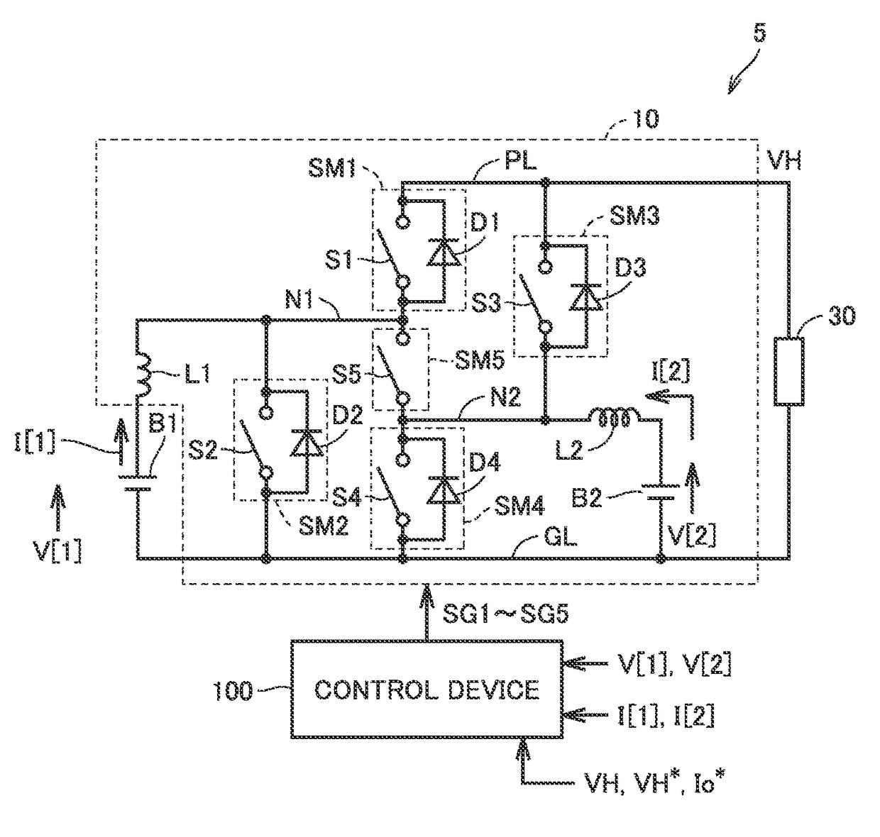
[0262]In a second embodiment, a modification of the circuit configuration of power converter 10 described in the first embodiment will be described. Specifically, a modification in which switching element S5 of power converter 10 shown in FIG. 1 is implemented by a bidirectional switch is shown.

[0263]FIG. 27 is a circuit diagram for illustrating a configuration of a power converter 11 according to the second embodiment.

[0264]Referring to FIG. 27, power converter 11 is different from power converter 10 shown in FIG. 1 in having a bidirectional switch SB5 instead of switching element S5 as a semiconductor element connected between nodes N1 and N2. Namely, bidirectional switch SB5 corresponds to “fifth semiconductor element SM5.” Since other features of power converter 11 are the same as those in power converter 10, detailed description will not be repeated.

[0265]Bidirectional switch SB5 has a diode D5a and a switching element S5a electrically connected in series between nodes N1 and N...

third embodiment

[0279]In a third embodiment, an operation mode other than the parallel boost mode of power converters 10 and 11 described in the first and second embodiments will be described.

[0280]FIG. 29 is a chart showing a list of a plurality of operation modes applied to power converters 10 and 11.

[0281]Referring to FIG. 29, the plurality of operation modes are broadly categorized into a “boost mode” in which output voltage VH is controlled in accordance with voltage command value VH* and a “direct coupling mode” in which on and off of switching elements S1 to S5 (S5a and S5b) is fixed and DC power supply (power supplies) B1 and / or B2 are / is electrically connected to power lines PL and GL.

[0282]The boost mode includes the parallel boost mode described above. In the parallel boost mode, by controlling on and off of switching elements S1 to S5 of power converter 10 in accordance with the gate Boolean expressions shown in FIG. 12, DC / DC conversion can be carried out in parallel between DC power s...


PUM


Abstract

A power supply system includes first and second DC power supplies and a power converter. The power converter includes first and third semiconductor elements electrically connected between respective nodes of a first node and a second node and a power line, second and fourth semiconductor elements electrically connected between respective nodes of the first node and the second node and a second power line, a fifth semiconductor element electrically connected between the first and second nodes, and first and second reactors. The first reactor is electrically connected in series with the first DC power supply, between the first node and the second power line. The second reactor is electrically connected in series with the second DC power supply, between the second power line and the second node. A control device controls on and off of the switching element included in the semiconductor element.

Description

[0001]This nonprovisional application is based on Japanese Patent Application No. 2015-140467 filed with the Japan Patent Office on Jul. 14, 2015, the entire contents of which are hereby incorporated by reference.BACKGROUND OF THE INVENTION[0002]Field of the Invention[0003]This invention relates to a power supply system, and more particularly to a power supply system configured to include a power converter connected between two direct-current (DC) power supplies and a common power line.[0004]Description of the Background Art[0005]A hybrid power supply system supplying, by using a power converter connected between a plurality of power supplies and a load, power supply to the load with the plurality of power supplies being combined, has been employed.[0006]For example, Japanese Patent Laying-Open No. 2013-46446 (Patent Document 1) describes a power supply system for a vehicle in which boost choppers (power converters) provided for each of a secondary battery and an auxiliary power sup...

Claims


Application Information

Patent Timeline
Patent Type & Authority Patents(United States)
IPC IPC(8): H02M3/158H02J7/00H02J1/00
CPCH02J1/00H02M3/158H02J7/0068H02J1/102Y02T10/70
Inventor TOMURA, SHUJIGOTO, SHIGEAKIYANAGIZAWA, NAOKIOKAMURA, MASAKITAKAMATSU, NAOYOSHI
Owner TOYOTA JIDOSHA KK
Why Eureka
Try Eureka