
Tire pressure detector with wheel balancing function and wheel balancing system thereof

a technology of tire pressure detection and function, which is applied in the direction of mechanical equipment, rotating body balancing, transportation and packaging, etc., can solve the problems of indirect tire pressure detection system not providing an actual tire pressure value to the driver, detection devices possessing a certain weight, and possible abnormal tire pressure of certain wheels, etc., to save a rather complicated installation procedure, facilitate installation easiness and convenience of use, and reduce vibration

Active Publication Date: 2020-06-09
CUB ELECPARTS
View PDF7 Cites 0 Cited by
  • Summary
  • Abstract
  • Description
  • Claims
  • Application Information

AI Technical Summary

Benefits of technology

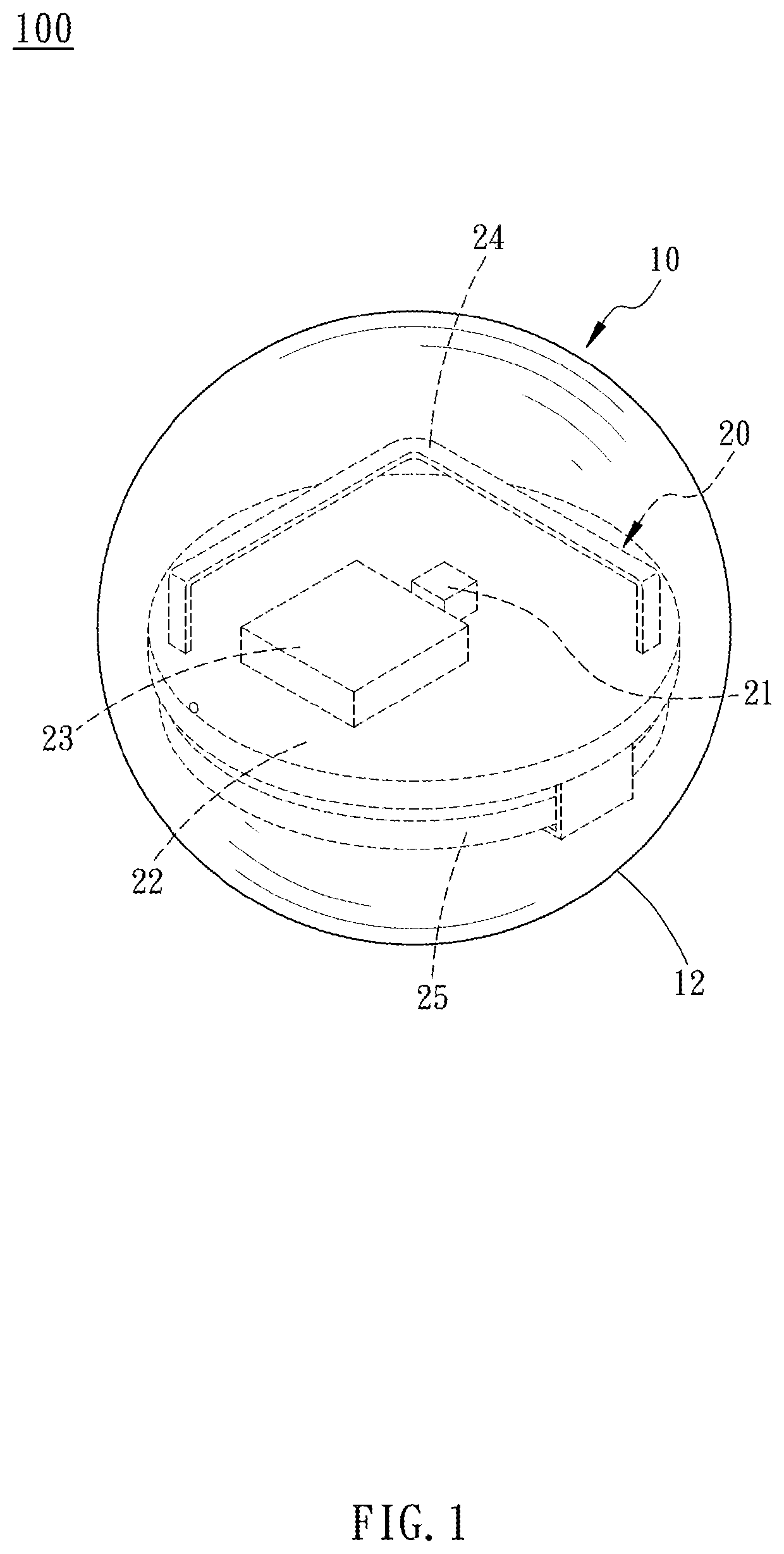
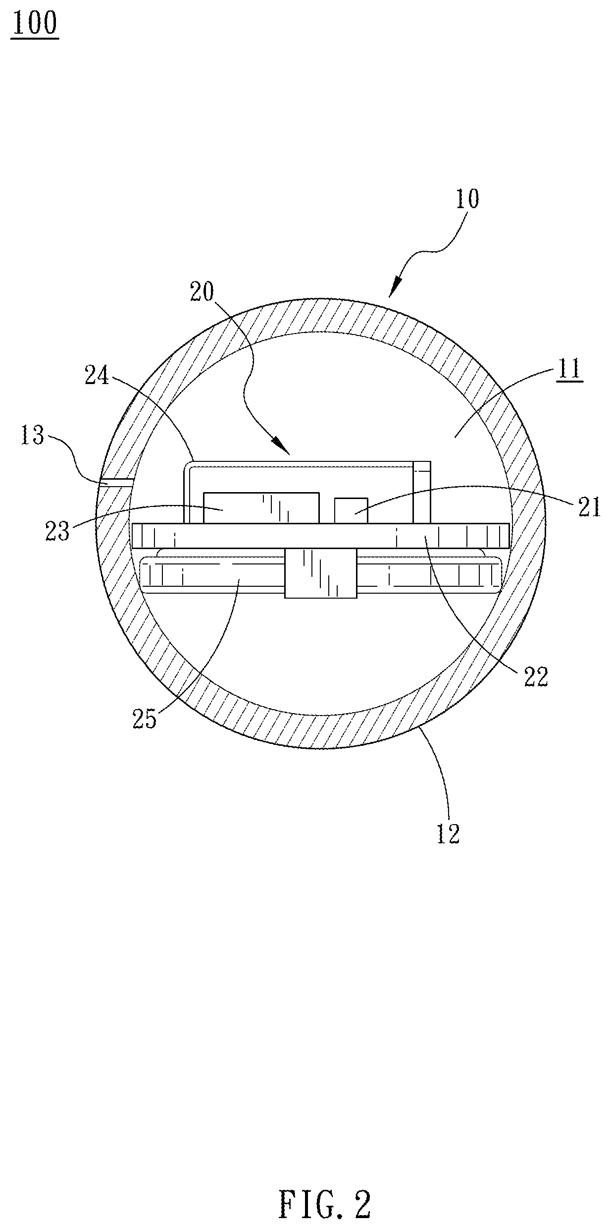
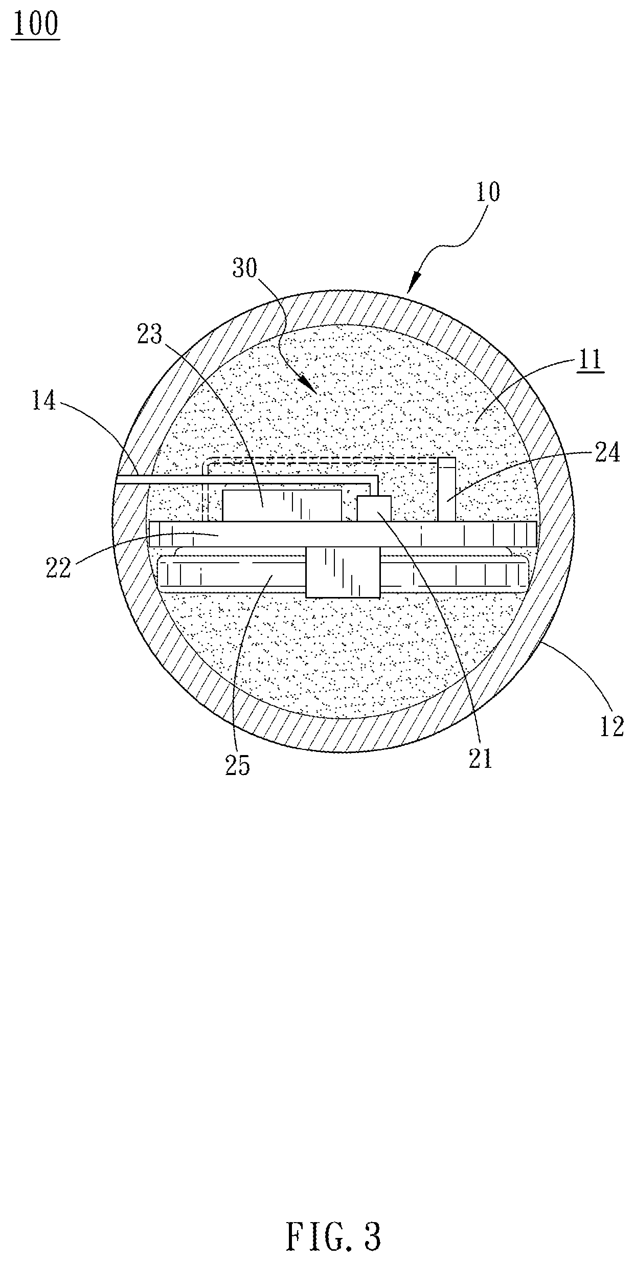
[0006]For improving the issues above, a tire pressure detector is disclosed. With the main body provided with the detection module disposed in the pressure space, the main body is allowed to move inside the tire during the movement of the vehicle, so as to balance the mass of the wheel, reduce the vibration thereof, and detect the air pressure in the pressure space through the detection module, thus achieving the wheel balancing and tire pressure detection functions.
[0010]With such configuration, the main body provided with the detection module is placed in the pressure space, such that the main body moves inside the tire during the movement of the wheel for detecting the pressure in the pressure space. Therefore, the detector does not need to be fixed on the tire, which may cause the unevenness of the wheel mass, and the wheel rebalancing process after the installation is omitted, saving a rather complicated installation procedure. Thus, the installation easiness and convenience of usage are facilitated.
[0011]Also, when the main body is able to move inside the tire during the movement of the wheel, a dynamic balance function is carried out to counteract the unbalancing vibration caused by the wheel and the related components, so as to balance the mass of the wheel and reduce the vibration thereof, thereby preventing the issues of wheel mass being affected by the tire pressure detection device and the imbalance and vibration of the wheel. Therefore, the present invention achieves both the wheel balancing and tire pressure detection function.
[0012]Further, the tire pressure detector in accordance with the present invention is simply placed in the pressure space between the tire and the rim for balancing the wheel and detecting the tire pressure, without the necessity of being disposed according to the specification of the wheel or the position of the air tap. Therefore, the present invention is applicable to various wheels, enhancing the scope of usage of the present invention.
[0013]A wheel balancing system applying the tire pressure detector in accordance with another embodiment of the present invention comprises a plurality of balancing members that are movably disposed in the pressure space together with the tire pressure detector. Therefore, the waving issue of the wheel is reduced to improve the balance of the wheel, such that the driving safety is enhanced.

Problems solved by technology

If the system detects the rotation speed of a certain wheel differs from the rotation speed of other wheels in a large degree, the tire pressure of the certain wheel might possibly be abnormal.
However, the indirect tire pressure detection system fails to provide an actual tire pressure value to the driver.
However, the detection device possesses a certain weight.
Also, the detection device shall be disassembled during the air filling process of the wheel, thus imposing a risk of damaging the detection device.
Further, when the air tap made of rubber material is combined with the external type detection device, the air tap might waves during the movement of the vehicle.
After a long duration, the rubber body of the air tap may possibly be broken.
Therefore, the internal type detection device usually has to be installed by a vehicle maintenance work, and the wheel shall be rebalanced after the installation of the internal type detection device.

Method used


Image

  • Tire pressure detector with wheel balancing function and wheel balancing system thereof
  • Tire pressure detector with wheel balancing function and wheel balancing system thereof
  • Tire pressure detector with wheel balancing function and wheel balancing system thereof

Examples


Embodiment Construction

[0021]The aforementioned and further advantages and features of the present invention will be understood by reference to the description of the preferred embodiment in conjunction with the accompanying drawings where the components are illustrated based on a proportion for explanation but not subject to the actual component proportion.

[0022]The amount of components defined by the texts “a”, “an”, and “the” used in the singular form includes the embodiments of the plurality forms in the present invention, unless being otherwise defined by the context of the specification. It shall be understood that the texts such as “include” and / or “comprise” indicate that such technical features, bodies, members, modules, and / or units exist among other technical features, bodies, members, modules, and / or units, instead of excluding the existence of others.

[0023]When one element / component is mentioned as being “on” or “above”, or being “connected”, “coupled with”, or “combined with” another element...


PUM


Abstract

A tire pressure detector disposed at a wheel, wherein the wheel includes a rim and a tire mounted around the rim, with a pressure space formed between the tire and the rim. The rim includes an air tap connected with the pressure space. The tire pressure detector includes a main body movably disposed in the pressure space and provided with a housing space, and a detection module disposed in the housing space. The detection module further includes a sensing unit for sensing the air pressure in the pressure space and producing a pressure signal. A central processing unit of the detection module receives the pressure signal and wirelessly transmits the pressure signal through the wireless transmission unit. Therefore, vibration and waving issue due to imbalance weight is avoided, thus balancing the wheel.

Description

BACKGROUND OF THE INVENTION1. Field of the Invention[0001]The present invention relates to tire pressure detection, and more particularly, to a tire pressure detector with wheel balancing function and wheel balancing system thereof.2. Description of the Related Art[0002]A tire detection system is an electronic system disposed at a vehicle wheel for detecting the sufficiency of pressure of the tire, whereby the variation of tire pressure is immediately monitored and displayed through a panel board, a digital displayer, or simple light signals, so as to prevent traffic accidents from occurring due to overpressure of the tire.[0003]The operation method of a tire detection system mainly comprises a direct type and an indirect type detection system. The indirect type tire pressure detection system, instead of directly detecting the tire pressure of a wheel, detects the rotation speed of the wheel. If the system detects the rotation speed of a certain wheel differs from the rotation speed...

Claims


Application Information

Patent Timeline
Patent Type & Authority Patents(United States)
IPC IPC(8): B60C19/00B60C23/04F16F15/36
CPCB60C19/003B60C23/0493B60C23/04B60C23/0447B60C23/0408F16F15/363
Inventor YU, SAN-CHUANHUNG, YUAN-TUNGLEE, KUO-TINGHUANG, KUAN-KAI
Owner CUB ELECPARTS
Learn More