Modular lightbar system and method

a lightbar system and modular technology, applied in the direction of semiconductor devices, lighting and heating apparatus, lightbar systems with an ssl light source, etc., can solve the problems of virtually trouble-free lightbar systems, long service life well beyond the expected life of incandescent or fluorescent light sources, etc., to achieve convenient installation, configuration and service, the effect of flexible configuration

Active Publication Date: 2020-06-16
MAXLITE
View PDF9 Cites 1 Cited by
  • Summary
  • Abstract
  • Description
  • Claims
  • Application Information

AI Technical Summary

Benefits of technology

[0006]The present invention is directed to a modular light system that overcomes the above-described shortcomings in the art. Specifically, in accordance with an embodiment of the present invention, and as an object of the present invention, a modular lightbar system is provided that is more flexibly configurable, enabling easy installation, configuration and service.
[0007]Such a design and configuration enables the lightbar assembly connector and lightbar assembly to be connected by moving the lightbar assembly connector in a direction generally transverse to the longitudinal axis of the lightbar assembly (or by moving the lightbar assembly in a direction generally transverse to the major surface of the lightbar assembly connector). It is thus possible, in accordance with embodiments of the present invention, to assemble a lightbar system comprised of a plurality of lightbar assemblies and lightbar assembly connectors, any of which are removable, replaceable, serviceable, etc., without having to disassemble the entire lightbar system. Any one component (e.g., lightbar assembly, lightbar assembly connector, etc.) may be removed and replaced simply, easily and safely.

Problems solved by technology

Lightbar systems with an SSL light source are virtually trouble-free, and last well beyond the expected life of incandescent or fluorescent light sources.
This presents significant problems for removing a lightbar assembly that is not located at an end of the lightbar system.

Method used


Image

  • Modular lightbar system and method
  • Modular lightbar system and method
  • Modular lightbar system and method

Examples


Embodiment Construction

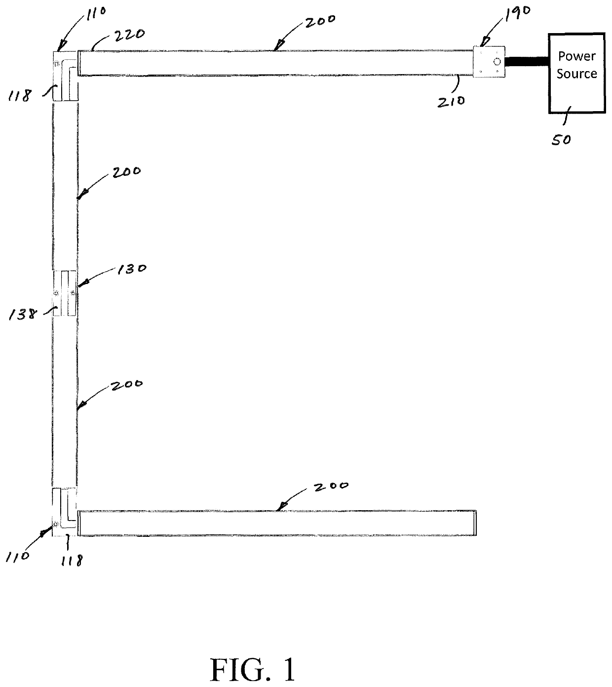
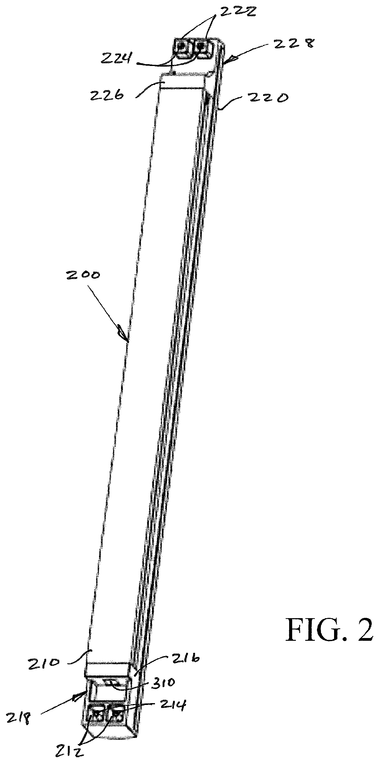
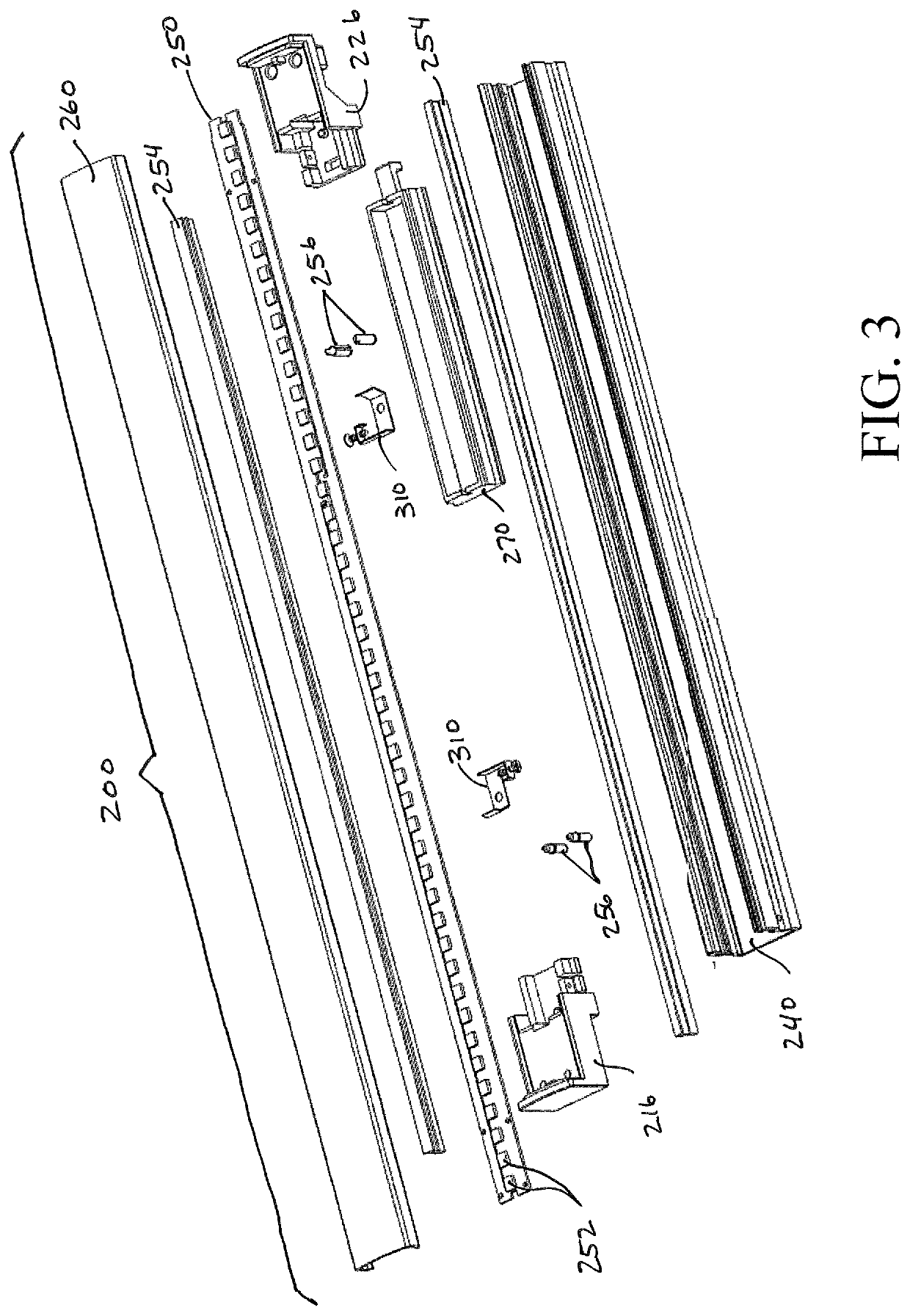
[0023]The present invention will now be described in detail and with reference to the drawing figures. Referring first to FIGS. 1-7, a lightbar system 100 in accordance with an embodiment of the present invention comprises a lightbar assembly 200 and at least a lightbar assembly connector 110, 130, 150, 170 or 190. The lightbar assembly connector may be a straight connector 130, and angle connector 110, a joiner assembly 150, a distribution box 170 or a power connector box 190. Each of these will be described in more detail below. The embodiment of FIG. 1 depicts a plurality of lightbar assemblies 200 connected by a plurality of lightbar assembly connectors 110, 130 to form a “S”, “Z”, “C”, or “U” shaped configuration. This depiction is exemplary only, and the present invention is flexibly and selectively configurable in countless configurations. Each lightbar assembly 200 has a receptacle end 210 and a plug end 220 that are located at longitudinally separated ends of the lightbar a...


PUM


Abstract

A modular light system comprising a lightbar assembly with first and second conductive parts, each of which extend in a direction generally transverse to a longitudinal axis of the lightbar assembly. The modular lightbar system further comprises a lightbar assembly connector having a major surface and with a conductive part that extends in a direction generally transverse to the major surface. Such a design and configuration enables the lightbar assembly connector and lightbar assembly to be connected by moving the lightbar assembly connector in a direction generally transverse to the longitudinal axis of the lightbar assembly (or by moving the lightbar assembly in a direction generally transverse to the major surface of the lightbar assembly connector). It is thus possible to assemble a lightbar system comprised of a plurality of lightbar assemblies and lightbar assembly connectors, any of which are removable, replaceable, or serviceable.

Description

CROSS-REFERENCE TO RELATED APPLICATION[0001]This application claims priority to U.S. Provisional Patent Application No. 62 / 489,586 filed Apr. 25, 2017, the contents of which are incorporated by reference herein.FIELD OF THE INVENTION[0002]The present invention relates to improvements to modular lightbar systems.BACKGROUND OF THE INVENTION[0003]Lightbar systems continue to increase in popularity and utility as they become easier to use and install, and cheaper to manufacture and operate. Using solid state lights (SSL) as the light source provides increased reliability and usable life, as well as simplicity of installation and service. Lightbar systems with an SSL light source are virtually trouble-free, and last well beyond the expected life of incandescent or fluorescent light sources.[0004]Lightbar systems typically comprise one or more lightbar assemblies connected in a desired layout, e.g., under-cabinet lighting in a kitchen, display cases, cove lighting, track lighting, and wal...

Claims


Application Information

Patent Timeline
Patent Type & Authority Patents(United States)
IPC IPC(8): F21S2/00F21V23/06F21V5/04F21V23/04F21V21/30F21V23/00F21Y103/10F21Y115/10
CPCF21V23/04F21V23/06F21S2/005F21V5/04F21Y2115/10F21V23/002F21V21/30F21V23/0442F21Y2103/10
Inventor CHAMI, AYMENTANG, YAOLIN
Owner MAXLITE
Why Eureka
Try Eureka