
Device and method for temporarily storing gas and heat

a technology for temporary storage and gas, applied in indirect heat exchangers, machines/engines, lighting and heating apparatus, etc., can solve the problems of inconvenient and inconvenient dynamic methods such as co-current or counter-current methods, and the inability to achieve adiabatic insulation of giant high-pressure vessels, and achieve the effect of increasing the effective pressur

Active Publication Date: 2020-06-23
APT GMBH - ANGEWANDTE PHYSIK & TECH
View PDF14 Cites 0 Cited by
  • Summary
  • Abstract
  • Description
  • Claims
  • Application Information

AI Technical Summary

Benefits of technology

[0022]Preferably the heat accumulators are thermally insulated from one another and / or with respect to the surroundings. Thermal equilibrium between the heat accumulators can thus be prevented.
[0026]According to one arrangement the predetermined minimum temperature of the first heat accumulator connected in series is 100° C., approximately 100° C., at least 100° C. and / or more than 100° C. In particular the heat storage medium of the first series-connected heat accumulator is glycerine (also called glycerol). Preferably exclusively glycerine is used as heat storage medium of the first series-connected heat accumulator. Glycerine (molecular formula: C3H8O3) occurs for example as a waste product in the production of biofuels and can therefore be obtained relatively cheaply.
[0030]Preferably the heat accumulator vessel of the first heat accumulator connected in series or at least the heat accumulator vessel of the first heat accumulator connected in series can be formed closed. In this way the development of fumes and / or vapour of glycerine, which occurs starting from ca. 150° C., can be counteracted. By means of the heating device and / or by maintaining the minimum temperature of the first heat accumulator connected in series it can in particular furthermore be ensured that during operation the temperature does not fall below the relatively high melting point of glycerine (melting point of glycerine=18° C.).
[0039]According to one arrangement the or several of the or at least one of the compressors also forms or form in particular an expansion device or in each case also an expansion device, by means of which the gas can be expanded. Preferably the or each compression stage, whose compressor is also formed as an expansion device, also forms an expansion stage. A compressor also formed as an expansion device is termed for example a combined compression and expansion machine. A combined compression and expansion machine includes for example a converted two-stroke diesel engine in the cylinder head, which operates as a compressor driven by an electric motor for storage and / or compression and generates compressed air. During recovery and / or expansion it operates as a compressed air motor and the electric motor becomes in particular an electric generator. This allows simple and compact systems. Also, turbine compressors can be realised.
[0042]According to a first variant the or several of the or at least one of the compressors forms / form in particular also the or respectively also one of the expansion devices (as already discussed above). In this way material savings can be made. According to a second variant the compressors and the expansion device or expansion devices form in particular devices and / or machines separate and / or different from one another. Accordingly the respective devices and / or machines can be optimally designed for their respective tasks.
[0059]In the first process stage the reduction of the pressure of the gas through the removal of heat by the heat accumulator arrangement on filling the pressure vessel reduces in particular the pressure of the gas in the pressure vessel and thus the resistance against which the compressors have to operate. In the second process stage the addition of heat produced by the heat accumulator arrangement on emptying the heat accumulator in the expansion increases the effective pressure, whereby the pressure vessel can be emptied in particular more slowly and the stored gas stock lasts longer.

Problems solved by technology

A dynamic method such as the co-current or counter-current method is however in this case not necessarily expedient, since the charging and discharging of the energy accumulator should as far as possible be chronologically decoupled from one another.
In practice it is probably not possible to accomplish the adiabatic insulation of a giant high-pressure vessel.
The fact is, if the thermal insulation were installed outside the pressure vessel, then the container wall would heat up.
On account of the enormous heat capacity of the pressure vessel the heat of compression would then simply result in a slight rise in temperature of the container wall and at this low temperature would largely be lost for a practicable, direct heat recovery.
Thermal insulation installed within the high-pressure vessel would on the other hand be subjected to enormous pressure and temperature fluctuations (several hundred bars, several hundred degrees Kelvin), which would destroy the insulation over time.
Another fundamental problem now arises: although heat can be efficiently transferred at high temperature differences and such temperature differences are in principle also advantageous in heat engines (see Carnot efficiency), the losses due to convection, conduction and in particular radiation however also increase correspondingly (proportional to the fourth power of the temperature, according to the Stefan-Boltzmann law).
High-temperature heat accumulator are in therefore principle unsuitable for longer periods of time, which however are basically desirable in energy storage.
A known high-temperature accumulator suffers inter alia also from the fact that the discussed high temperature and pressure differences mechanically degrade the storage material (e.g. stone) and the resulting particles can on expansion sandblast the turbine blades.
Phase change materials (PCM) are not suitable for the temperature differences occurring in practice or are still in the experimental stage.
They degrade over time and would therefore not be sufficiently efficient according to the present state of scientific knowledge.
Also, the known industrial adsorption storage materials silica gel and zeolite are not suitable, since a large portion of the heat of compression is below the discharge temperatures and the heat transfer is a continuous and not a discrete process.

Method used


Image

  • Device and method for temporarily storing gas and heat

Examples


Embodiment Construction

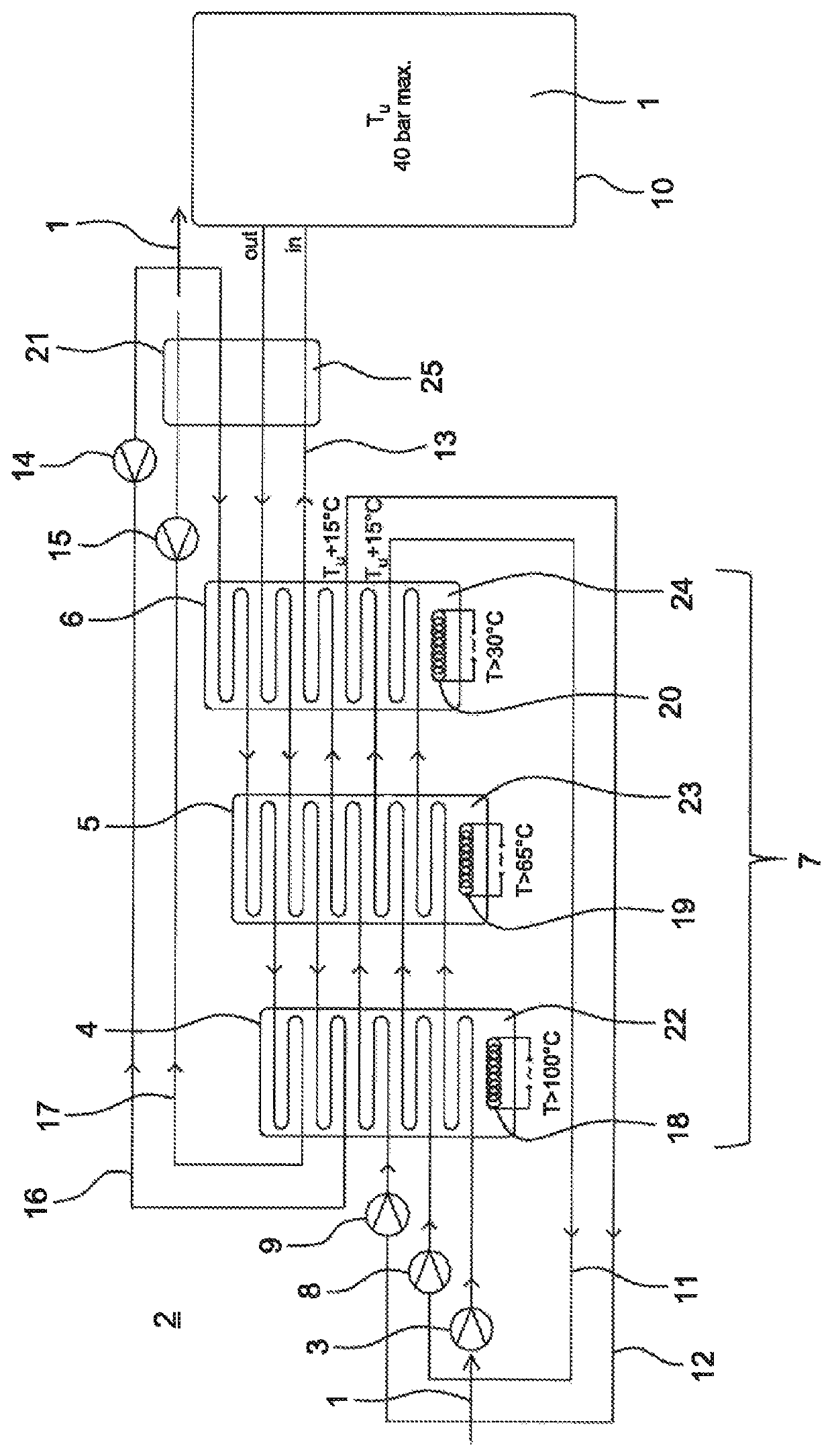
[0077]FIG. 1 shows a schematic representation of a device according to an embodiment of the invention, in which air 1 from the surroundings 2 is compressed by means of a first compressor 3 and then passes in succession through a plurality of heat accumulators 4, 5 and 6 of a heat accumulator arrangement 7. After this the air 1 is additionally compressed by a second compressor 8 and then passes in succession through the heat accumulators 4, 5 and 6. The compressed air is then compressed further by a third compressor 9 and next passes in succession through the heat accumulators 4, 5 and 6. The air 1 is then stored in a pressure vessel 10. The respective flow direction of the air 1 is represented by arrows and arrow heads. The compressors 3, 8 and 9 are also termed compressors.

[0078]A gas flow path is connected downstream of each compressor, which together with the respective compressor forms a compression stage. Thus, the gas flow path 11 is connected downstream of the compressor 3, t...


PUM


Abstract

A device for temporary storage of gas and heat includes a plurality of compressors for compressing a gas, a plurality of compression stages connected in series, each compression stage including one of the plurality of compressors and a gas flow path connected downstream of the one of the plurality of compressors, at least one pressure vessel connected downstream of a last compression stage of the plurality of compression stages in the series for storing the gas compressed by the plurality of compressors, and a heat accumulator arrangement including a plurality of heat accumulators connected in a heat accumulator sequence for storing the heat generated by the compression of the gas, the gas flow path of each compression stage passing through the heat accumulators in succession in the heat accumulator sequence.

Description

REFERENCE TO RELATED APPLICATIONS[0001]This application is a U.S. National Stage of PCT / EP2015 / 075494, filed Nov. 2, 2015, which claims priority from German Application No. DE102014118466.1, filed Dec. 11, 2014, the entire content of both of which is incorporated herein by reference.FIELD OF THE INVENTION[0002]The invention relates to a device for the temporary storage of gas and heat, with at least one pressure vessel, a plurality of compressors by means of which a gas can be compressed, a plurality of compression stages connected in series, each of which includes one of the compressors and a gas flow path connected downstream of the latter, wherein the pressure vessel is connected downstream of a last of the series-connected compression stages, in which the gas compressed by means of the compressor can be stored, and a heat accumulator arrangement comprising a plurality of heat accumulators, by means of which the heat of compression generated by the compression of the gas can be s...

Claims


Application Information

Patent Timeline
Patent Type & Authority Patents(United States)
IPC IPC(8): F02C6/16F28D20/00
CPCF02C6/16Y02E60/15F28D2020/0004F28D20/0034Y02E20/14Y02E60/14Y02E60/16
Inventor GEISLER, BERND
Owner APT GMBH - ANGEWANDTE PHYSIK & TECH
Learn More