Tubing or annulus pressure operated borehole barrier valve

a technology of pressure operated and borehole, which is applied in the direction of sealing/packing, borehole/well accessories, construction, etc., can solve the problems of control line or line used to actuate the barrier valve or safety valve, damage to the control line or safety valve, and risk of loss of use of the barrier valv

Active Publication Date: 2020-07-07
BAKER HUGHES INC
View PDF32 Cites 2 Cited by
  • Summary
  • Abstract
  • Description
  • Claims
  • Application Information

AI Technical Summary

Problems solved by technology

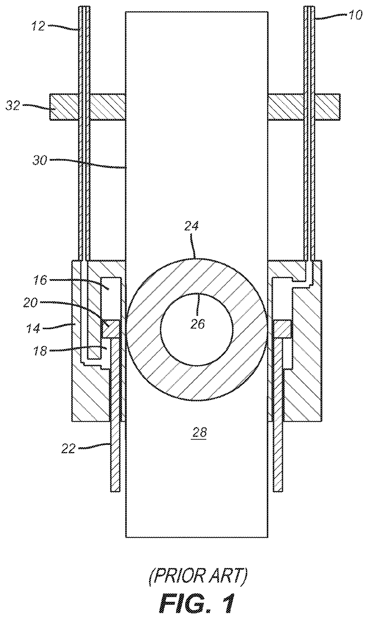
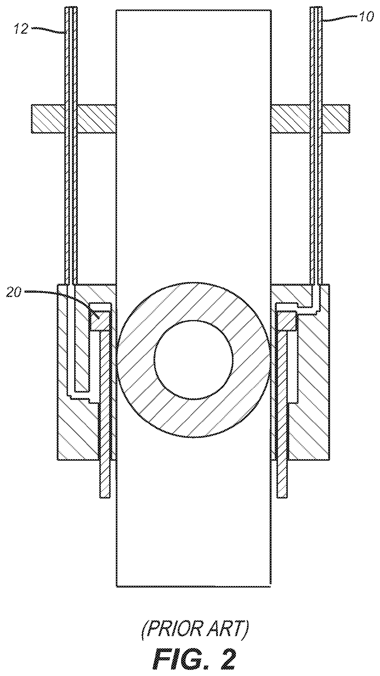
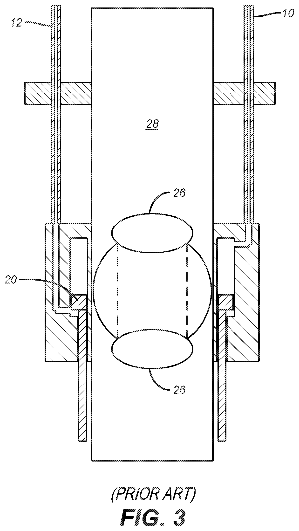
As wells get deeper and deeper a concern has arisen among operators that the control line or lines that are used to actuate the barrier valves or safety valves can be damaged when running in the tubular string.
As previously explained there are installations, particularly offshore where depths can get to 10,000 meters and beyond and the deep placement of the barrier valve to meet regulations for redundant isolation entails long control line runs that not only slow the tripping into the hole procedure but also present a risk of loss of use of the barrier valve if one or both control lines is damaged when running into hole.

Method used


Image

  • Tubing or annulus pressure operated borehole barrier valve
  • Tubing or annulus pressure operated borehole barrier valve
  • Tubing or annulus pressure operated borehole barrier valve

Examples


Embodiment Construction

[0017]Referring to FIG. 4, the valve member 24 is omitted so that other parts of the actuation system can be more dearly illustrated. The actuation piston 20 with opposed chambers 16 and 18 are the same as described in FIGS. 1-3. The pressure that will ultimately move the piston 20 is different than in FIG. 1-3 where control lines 10 and 12 running from a surface location were used. Instead there are two alternative sources of fluid actuation pressure. One source is dashed line 34 that starts through the wall of the tubular string 30. The other alternative source is the upper annulus 36 using a line 38 that just comes through the production packer 32. Line 38 gives access to the upper annulus 36 from a surface location to inlet 40 of manifold assembly 42. Alternatively the tubing string 30 is the source of pressure through line 34 that is connected to inlet 40.

[0018]Manifold assembly 42 has an inlet line 44 that branches to lines 46 and 48. Line 46 leads to chamber 16 and line 48 le...


PUM


Abstract

An operating system for a barrier valve or safety valve is responsive to increments in annulus or tubing pressure. An indexing device controls valves that selectively direct pressure applied to one side of an operating piston or the other for attaining the open and closed positions of the barrier valve. One such indexing device can be a j-slot. Other devices that operate a pair of hydraulic valves in tandem for pressure direction to one side of an actuation piston or another are contemplated. The system needs no electric power and there are no control lines needed to run below the production packer in the case of using annulus pressure to actuate the piston or at all if access to tubing pressure is provided from the vicinity of the barrier valve components.

Description

FIELD OF THE INVENTION[0001]The field of the invention is deep set barrier valves in a borehole and more particularly where the actuation is accomplished with cycled tubing or annulus pressure in conjunction with an indexing device to avoid the need for external control lines outside the tubular string to the barrier valve.BACKGROUND OF THE INVENTION[0002]Typically barrier valves or subsurface safety valves are put in a tubular string thousands of meters below a surface location and operated by one or more control lines. As wells get deeper and deeper a concern has arisen among operators that the control line or lines that are used to actuate the barrier valves or safety valves can be damaged when running in the tubular string. Typically control systems for such valves have a one line or two line system to an actuation piston that operates the barrier valve. A two line system is pressure balanced from the perspective of control line hydrostatic pressure because the lines run paralle...

Claims


Application Information

Patent Timeline
Patent Type & Authority Patents(United States)
IPC IPC(8): E21B34/14E21B23/00E21B34/08E21B34/10E21B34/00
CPCE21B34/08E21B34/101E21B34/14E21B23/004E21B2200/04E21B34/06E21B34/10
Inventor JOHNSON, MICHAEL H.JACKSON, TODD C.
Owner BAKER HUGHES INC
Why Eureka
Try Eureka