Fixed-point dragging continuous liquid drainage tubular column for fixed-point dragging of offshore low-pressure gas well and liquid drainage method of fixed-point dragging continuous liquid drainage tubular column

A technology of drainage pipe and low-pressure gas, which is used in earth-moving drilling, wellbore/well components, and production fluids, etc., can solve the problems of reservoir damage, high construction operation cost, and insignificant liquid drainage effect, and achieves easy portability. Liquid effect, damage avoidance effect

Pending Publication Date: 2022-04-05
CHINA NAT OFFSHORE OIL CORP +2
View PDF16 Cites 2 Cited by
  • Summary
  • Abstract
  • Description
  • Claims
  • Application Information

AI Technical Summary

Problems solved by technology

[0005] The present invention overcomes the deficiencies in the prior art, such as the insignificant drainage effect of gas wells with low pressure coefficient and horizontal accumulation of liquid in the sea, the high construction cost of the drainage and production string, and the technical problems that the drainage and production measures cause damage to the reservoir, and provides a new solution. An offshore low-pressure gas well fixed-point dragging continuous liquid drainage string and its liquid drainage method. The liquid drainage string has technical advantages such as remarkable liquid drainage effect and reliable construction operation in the drainage and production of low pressure coefficient horizontal gas wells.

Method used


Image

  • Fixed-point dragging continuous liquid drainage tubular column for fixed-point dragging of offshore low-pressure gas well and liquid drainage method of fixed-point dragging continuous liquid drainage tubular column
  • Fixed-point dragging continuous liquid drainage tubular column for fixed-point dragging of offshore low-pressure gas well and liquid drainage method of fixed-point dragging continuous liquid drainage tubular column
  • Fixed-point dragging continuous liquid drainage tubular column for fixed-point dragging of offshore low-pressure gas well and liquid drainage method of fixed-point dragging continuous liquid drainage tubular column

Examples


Embodiment 1

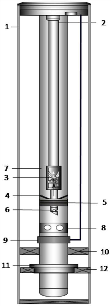
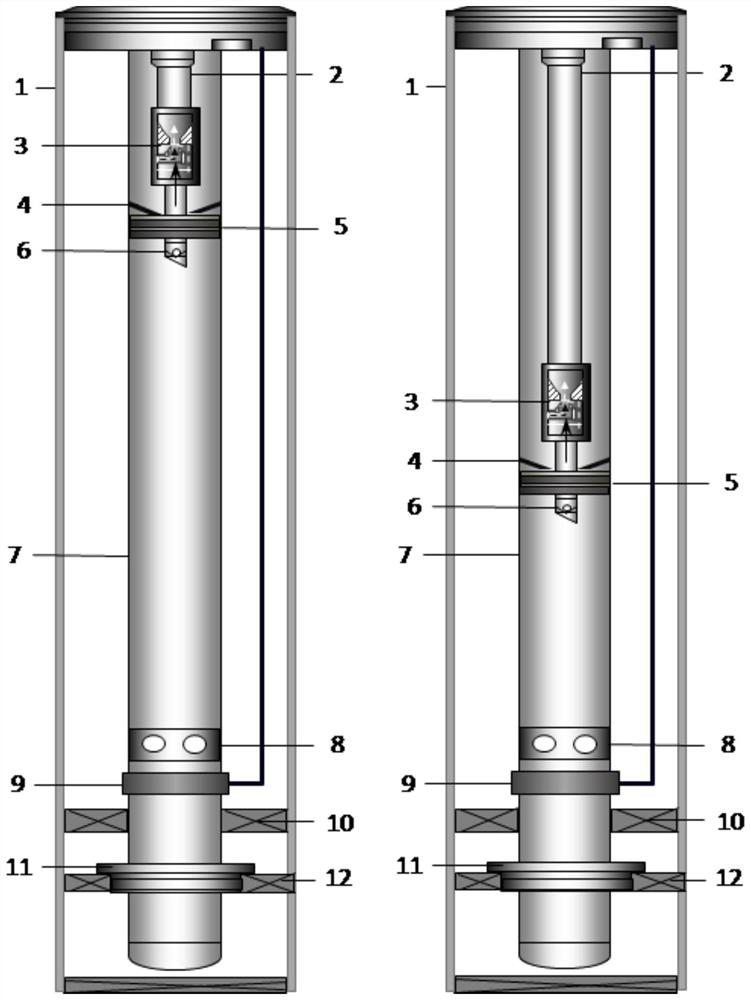
[0029] An offshore low-pressure gas well fixed-point dragging continuous liquid drainage string, including casing 1, coiled tubing 2, gas injection pump 3, in-pipe packer 5, check valve 6, production tubing 7, circulation slide Set 8, deep well safety valve 9, production packer 10, positioning seal 11 and top packer 12;

[0030] The production tubing 7 is set inside the casing 1, the top packer 12 is set between the inner wall of the tail end of the casing 1 and the outer wall of the tail end of the production tubing 7, and a positioning seal is set on the production tubing 7 above the top packer 12 11. On the production tubing 7 above the positioning seal 11, a deep well safety valve 9 and a circulating sliding sleeve 8 are arranged in sequence from bottom to top. The deep well safety valve 9 is used to ensure the emergency safety protection of the fluid in the offshore gas well tubing, and the circulating sliding sleeve 8 is used for During offshore gas well operation, a pro...

Embodiment 2

[0035] On the basis of Embodiment 1, an anti-sand cup 4 is provided between the inner wall of the production tubing 7 above the inline packer 5 and the outer wall of the coiled tubing 2 to prevent sand from accumulating on the inline packer 5 surface to ensure the success rate of lifting and lowering operation of the inner pipe packer 5.

[0036] The inner diameter of the coiled tubing 2 is 1.5, 1.75 or 2 inches.

[0037] Finally, by adopting three types of coiled tubing with an inner diameter of 2, 1.75 or 1.5 inches, because of its smaller inner diameter, the critical liquid-carrying capacity of gas wells in the coiled tubing can be greatly increased, and the liquid drainage function of the velocity string can be greatly improved. Has a good liquid carrying effect.

Embodiment 3

[0039] A method for draining liquids by dragging a continuous draining string at a fixed point without moving a string in an offshore low-pressure gas well, which is carried out according to the following steps:

[0040] Step 1, wellhead treatment: remove the Christmas tree, install the riser, connect the blowout preventer, and tie back the control pipeline;

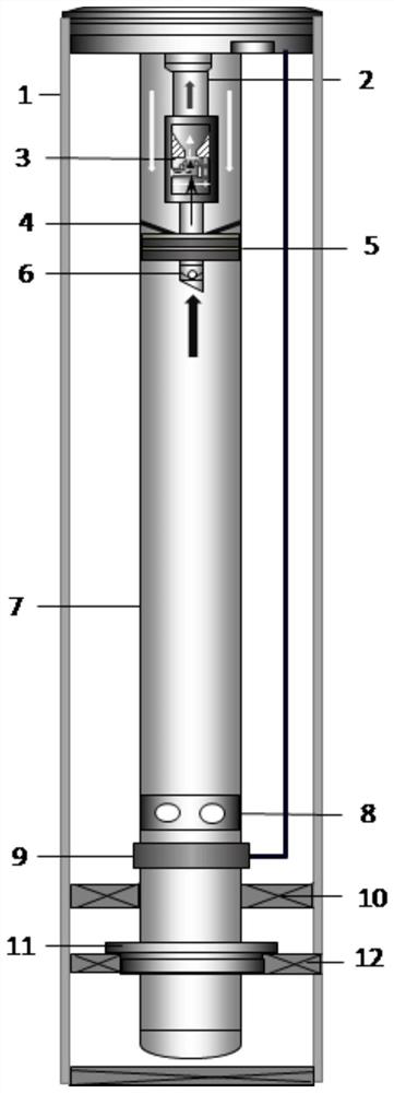
[0041] Step 2, run the coiled tubing: run the coiled tubing connected with the in-line packer and the gas injection pump to the predetermined depth H 1 ;

[0042] Step 3, setting the inner tubing packer: setting the inner tubing packer by lowering the pressure of the coiled tubing, and simultaneously establishing a semi-closed annular space between the inner wall of the production tubing and the outer wall of the coiled tubing;

[0043] Step 4, injecting high-pressure gas for continuous liquid drainage: After the in-line packer is set, inject high-pressure gas directly into the semi-closed annular space between the inne...


PUM


Abstract

The invention provides an offshore low-pressure gas well immovable string fixed-point dragging continuous liquid drainage string and a liquid drainage method thereof.A production oil pipe is arranged in a sleeve, a top packer is arranged between the inner wall of the tail end of the sleeve and the outer wall of the tail end of the production oil pipe, and a positioning seal is arranged on the production oil pipe above the top packer; a deep well safety valve and a circulating sliding sleeve are sequentially arranged on the portion, above the positioning seal, of the production oil pipe from bottom to top, a production packer is arranged between the inner wall of the casing pipe and the outer wall of the production oil pipe, an in-pipe packer is arranged in the production oil pipe, a continuous oil pipe is arranged in the production oil pipe, and the tail end of the continuous oil pipe penetrates through the in-pipe packer. A check valve is arranged at the tail end of the continuous oil pipe and located below the in-pipe packer, and a gas jet pump is arranged on the continuous oil pipe above the in-pipe packer. The liquid drainage pipe column has the technical advantages of being remarkable in liquid drainage effect, reliable in construction operation and the like in the aspect of low-pressure-coefficient horizontal gas well drainage.

Description

technical field [0001] The invention relates to the technical field of oil field exploitation, and more specifically relates to a non-moving pipe string of an offshore low-pressure gas well and a fixed-point dragging continuous liquid discharge pipe string and a liquid discharge method thereof. Background technique [0002] During the exploitation of offshore gas fields, when the gas production rate of the gas well is lower than the critical liquid-carrying flow rate, the gas well begins to accumulate liquid, and the liquid accumulation in the wellbore of the gas well will increase the back pressure on the gas layer, severely limiting the productivity of the gas well. Especially once the wellbore of a low-pressure gas well accumulates fluid, the amount of fluid accumulated in the wellbore will continue to increase, and in severe cases, it will cause the low-pressure gas well to be flooded and stop production. [0003] Commonly used drainage techniques for offshore gas wells ...

Claims


Application Information

Patent Timeline
Patent Type & Authority Applications(China)
IPC IPC(8): E21B33/064E21B23/00E21B23/06E21B43/08E21B43/22
Inventor 郑春峰杨万有崔澎涛李昂詹敏谢双喜卞涛祖健蔡振华苏作飞周小林晁圣棋
Owner CHINA NAT OFFSHORE OIL CORP
Why Eureka
Try Eureka