Supercharge Your Innovation With Domain-Expert AI Agents!

Liquid level detecting device

a detection device and liquid level technology, applied in the direction of measurement devices, level indicators, instruments, etc., can solve the problem of low detection accuracy of liquid surface level, and achieve the effect of increasing the rotation angle range of the holder and high detection accuracy

Active Publication Date: 2020-07-07
YAZAKI CORP
View PDF4 Cites 0 Cited by
  • Summary
  • Abstract
  • Description
  • Claims
  • Application Information

AI Technical Summary

Benefits of technology

The present invention provides a liquid level detecting device that can increase the rotation angle range of the holder while maintaining high detection accuracy. This is achieved by designing the holder with flanges that prevent the holder from coming off the sensor housing and support projections that stabilize the holder's posture. The support projections have a play-preventive flange that increases the area of contact with the sensor housing, making the device more reliable in terms of product durability. Overall, the invention improves the liquid level detecting device's ease of installation and reliability.

Problems solved by technology

However, if the number of holder projection pieces is decreased, the holding of the holder by the recess of the sensor housing may become unstable to cause much play and a resulting holder rotation failure may lower the accuracy of detection of a liquid surface level.

Method used


Image

  • Liquid level detecting device
  • Liquid level detecting device
  • Liquid level detecting device

Examples


Embodiment Construction

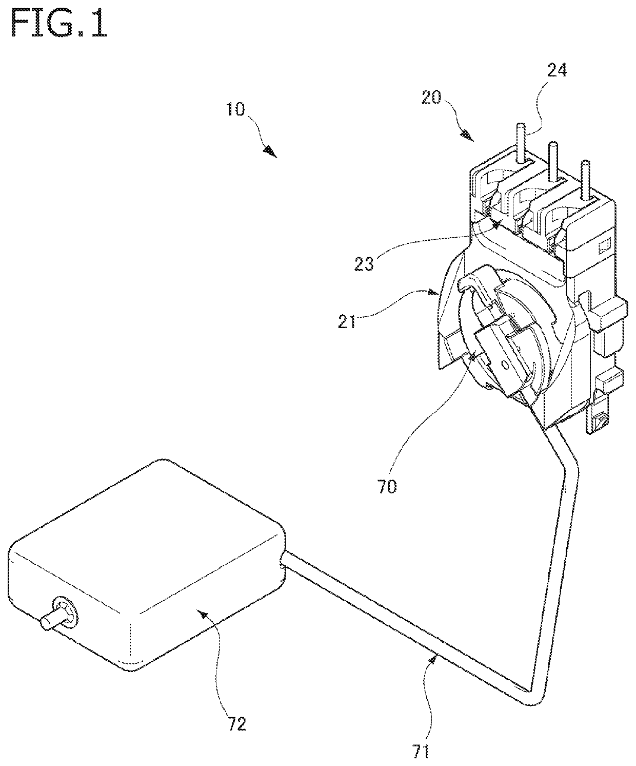
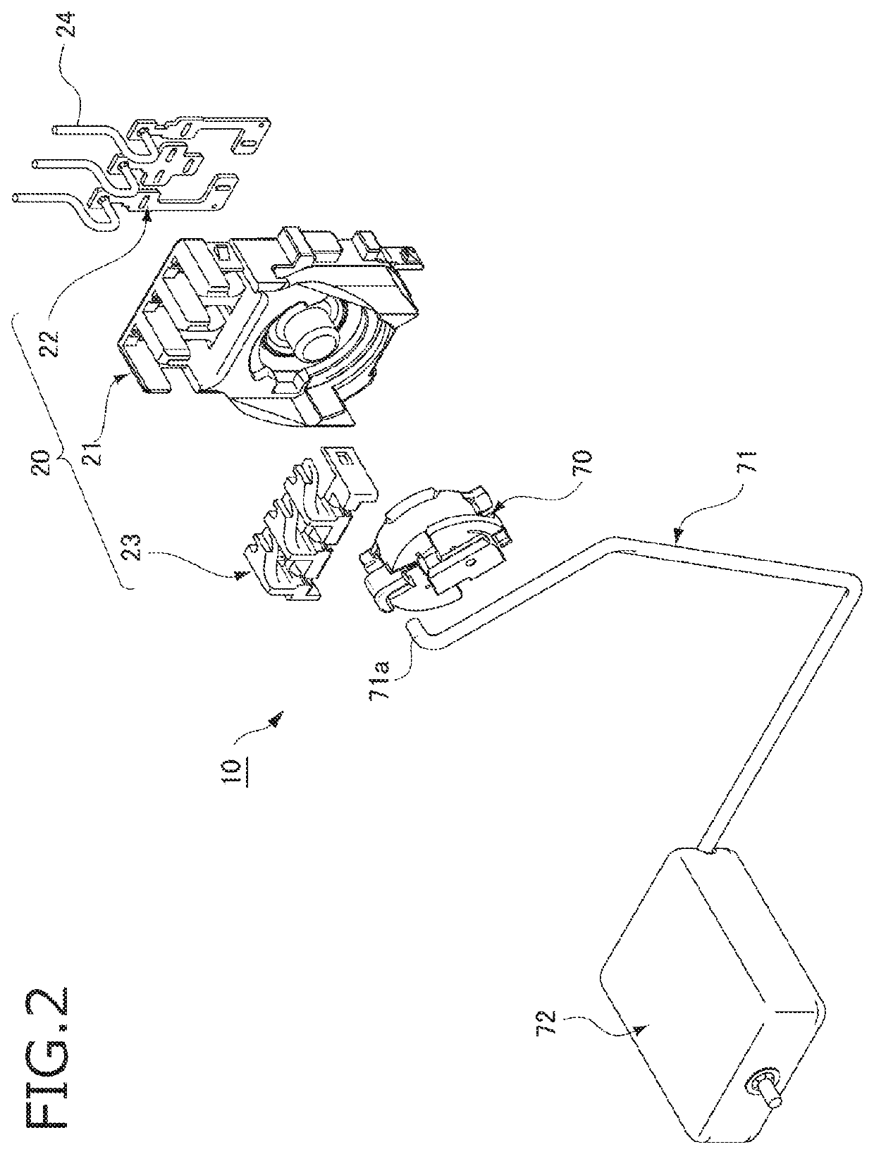
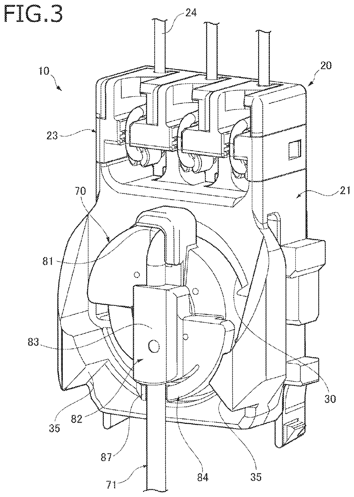
[0042]An embodiment of the present invention will be hereinafter described with reference to the drawings. FIG. 1 is a perspective view of the whole of a liquid level detecting device 10 according to the embodiment. FIG. 2 is an exploded perspective view of the liquid level detecting device 10. FIG. 3 is a perspective view of an essential part of the liquid level detecting device 10. FIG. 4 is a sectional view of the liquid level detecting device 10.

[0043]As shown in FIGS. 1 and 2, the liquid level detecting device 10 according to the embodiment includes a device main body 20, a holder 70, a float arm 71, and a float 72. The device main body 20 includes a sensor housing 21, a terminal 22, and a holding member 23.

[0044]As shown in FIGS. 3 and 4, the terminal 22 and the holding member 23 are attached to the sensor housing 21. A lead 26 of a Hall element 25 which is provided inside the sensor housing 21 is electrically connected to the terminal 22. Detection wires 24 which are held by ...


PUM


Abstract

A liquid level detecting device includes a sensor housing having a circular rotation recess, a circular holder which is fitted in the rotation recess and held rotatably by the sensor housing, a float arm, a float, a magnet, and a Hall element. The sensor housing has a lock groove and a pair of insertion holes. The holder has a pair of flanges which project in opposite directions from an outer circumferential surface of the holder and are engaged with the lock groove and prevented from coming off the rotation recess by setting the flanges opposed to the respective insertion holes, fitting the flanges into the rotation recess, and then rotating the flanges. The holder has a pair of support projections which come into contact with a bottom surface of the rotation recess.

Description

CROSS REFERENCE TO RELATED APPLICATIONS[0001]This application is based on Japanese Patent Application (No. 2017-111089) filed on Jun. 5, 2017 and Japanese Patent Application (No. 2018-045754) filed on Mar. 13, 2018, the contents of which are incorporated herein by reference.BACKGROUND OF THE INVENTION1. Field of the Invention[0002]The present invention relates to a liquid level detecting device.2. Description of the Related Art[0003]Liquid level detecting devices for detecting a level of a liquid stored in a tank are equipped with a device main body having a Hall element, a holder in which a magnet is provided so as to be rotatable with respect to the device main body, a float arm whose base portion is attached to the holder, and a float that is attached to a tip portion of the float arm (refer to JP-B-5382855 for example).[0004]A sensor housing that is a component of the device main body is formed with a recess in which the holder is held rotatably. The holder is formed with, on it...

Claims


Application Information

Patent Timeline
Patent Type & Authority Patents(United States)
IPC IPC(8): G01F23/38G01F23/60
CPCG01F23/38G01F23/603G01F23/363
Inventor HIROSE, RYONAKAJIMA, SHINTAROKATO, SHINPEI
Owner YAZAKI CORP
Features
  • R&D
  • Intellectual Property
  • Life Sciences
  • Materials
  • Tech Scout
  • Unparalleled Data Quality
  • Higher Quality Content
  • 60% Fewer Hallucinations
Learn More