Supercharge Your Innovation With Domain-Expert AI Agents!

Micromirror structure

A technology of micro-bridge structure and micro-mirror, which is applied in the direction of optical components, optics, instruments, etc., can solve the problems that cannot meet the requirements of the market, the rotation angle and direction are limited, and achieve the effect of improving the range of rotation angle and expanding the scanning range

Active Publication Date: 2019-07-09
SHANGHAI INTEGRATED CIRCUIT RES & DEV CENT
View PDF16 Cites 4 Cited by
  • Summary
  • Abstract
  • Description
  • Claims
  • Application Information

AI Technical Summary

Problems solved by technology

However, the rotation angle and direction of traditional micromirror devices are relatively limited, which is increasingly unable to meet market requirements

Method used


Image

  • Micromirror structure
  • Micromirror structure
  • Micromirror structure

Examples


Embodiment Construction

[0019] The specific embodiment of the present invention will be further described in detail below in conjunction with the accompanying drawings.

[0020] It should be noted that, in the following specific embodiments, when describing the embodiments of the present invention in detail, in order to clearly show the structure of the present invention for the convenience of description, the structures in the drawings are not drawn according to the general scale, and are drawn Partial magnification, deformation and simplification are included, therefore, it should be avoided to be interpreted as a limitation of the present invention.

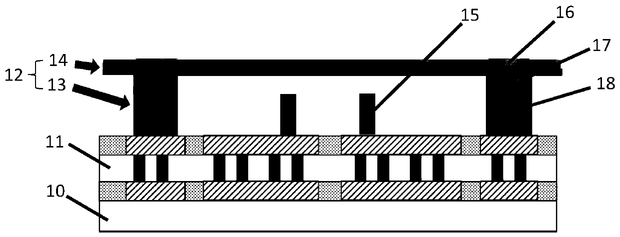
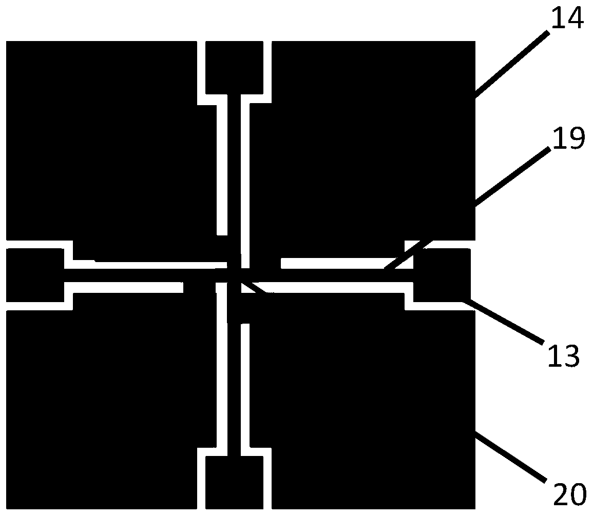
[0021] In the following specific embodiments of the present invention, please refer to figure 1 , figure 1 It is a schematic diagram of a micromirror structure in a preferred embodiment of the present invention. like figure 1 As shown, a micromirror structure of the present invention includes a micromirror array composed of micromirror units. Whe...


PUM


Abstract

The invention discloses a micromirror structure, which comprises a micromirror array consisting of micromirror units, wherein each micromirror unit consists of a plurality of microbridge structures which are in adjacent arrangement and are built on a substrate; each microbridge structure comprises a support post and a microbridge deck; the support post is arranged on the substrate in a connectingway; the microbridge deck forms single-point connection with the support post; a metal reflection layer is arranged on the microbridge deck, and builds electric connection with the substrate through the support post; at least one metal control component building electric connection with the substrate is arranged on the substrate arranged under each microbridge deck; when current is introduced to the metal reflection layer and the corresponding metal control component, the tilting direction and angle of each microbridge deck can be respectively controlled through voltage; the free rotation of the micromirror unit in a plurality of directions is realized, so that the rotating angle range of the micromirror can be improved; and when the micromirror structure is applied to laser radar, the scanning range of the laser radar can be obviously expanded.

Description

technical field [0001] The invention relates to the technical field of semiconductor integrated circuits and sensors, and more particularly, to a micromirror structure that can be rotated arbitrarily. Background technique [0002] With the development of autonomous driving technology, higher and higher requirements are put forward for lidar and its micromirror technology. However, the rotation angle and direction of traditional micromirror devices are relatively limited, which is increasingly unable to meet market requirements. Contents of the invention [0003] The object of the present invention is to overcome the above-mentioned defects in the prior art and provide a micromirror structure. [0004] To achieve the above object, the technical scheme of the present invention is as follows: [0005] A kind of micromirror structure, comprises the micromirror array that is made up of micromirror unit, and described micromirror unit is made up of the microbridge structure th...

Claims


Application Information

Patent Timeline
Patent Type & Authority Applications(China)
IPC IPC(8): G02B26/08
CPCG02B26/0833
Inventor 康晓旭
Owner SHANGHAI INTEGRATED CIRCUIT RES & DEV CENT
Features
  • R&D
  • Intellectual Property
  • Life Sciences
  • Materials
  • Tech Scout
  • Unparalleled Data Quality
  • Higher Quality Content
  • 60% Fewer Hallucinations
Learn More