Wheel-force dynamometer for measuring tire forces

a dynamometer and tire technology, applied in the direction of shaft and bearing, bearings, structural/machine measurement, etc., can solve problems such as measurement errors, and achieve the effects of increasing the rigidity of the bearing system, increasing the rigidity of the bearing design, and minimal friction

Active Publication Date: 2020-07-07
ZF FRIEDRICHSHAFEN AG
View PDF36 Cites 0 Cited by
  • Summary
  • Abstract
  • Description
  • Claims
  • Application Information

AI Technical Summary

Benefits of technology

[0006]The invention relates to a wheel-force dynamometer for the measurement by means of force sensors of forces and torques acting on a vehicle tire and a vehicle wheel, wherein the vehicle wheel is mounted and can rotate on a wheel axle. The wheel-force dynamometer according to the invention is characterized in that the wheel axle is in the form of a compact rotor which is mounted axially fixed and able to rotate in the circumferential direction in a rigid and positionally fixed housing. Since the wheel axle is no longer made solid and mounted inside a hollow shaft—as in the prior art—but, according to the invention, is in the form of a compact rotor held in a housing, by virtue of the larger diameter and annular cross-section of the housing, a maximum modulus of resistance and thus high rigidity is achieved. Moreover the mass of the wheel axle is reduced. Furthermore a housing that is rigid and does not rotate is provided, which accommodates the compact rotor. The positionally fixed housing in combination with the compact rotor provides an exceptionally rigid wheel mounting which deforms very little under the action of the tire forces that occur during the measurements. The invention is based on the recognition that a reason for measurement errors relates to a relatively low natural frequency of the measurement device compared with the measurement frequencies which are desirable in the context of a so-termed High Speed Uniformity (HSU) measurement. Thanks to the compact rotor and rigid housing that constitute the wheel mounting according to the invention, high rigidity and hence a relatively high natural frequency of the wheel-force dynamometer are obtained. The occurrence of resonances at the measurement frequencies can therefore be avoided, since the measurement frequencies are lower than the natural frequencies of the wheel mounting. This results in optimized transfer functions, which show smaller amplitude increases and smaller phase shifts.
[0019]In a further preferred embodiment of the invention, it is provided that the housing body has a stud that engages in the rotor at least in the area of the collar. On the one hand this additionally supports the mounting of the rotor in the housing, and on the other hand it further increases the rigidity of the wheel-force dynamometer.

Problems solved by technology

During the measurement of tire forces by a wheel-force dynamometer, measurement errors can occur, which are determined by the design of the measuring device and its vibration behavior.

Method used


Image

  • Wheel-force dynamometer for measuring tire forces
  • Wheel-force dynamometer for measuring tire forces
  • Wheel-force dynamometer for measuring tire forces

Examples


Embodiment Construction

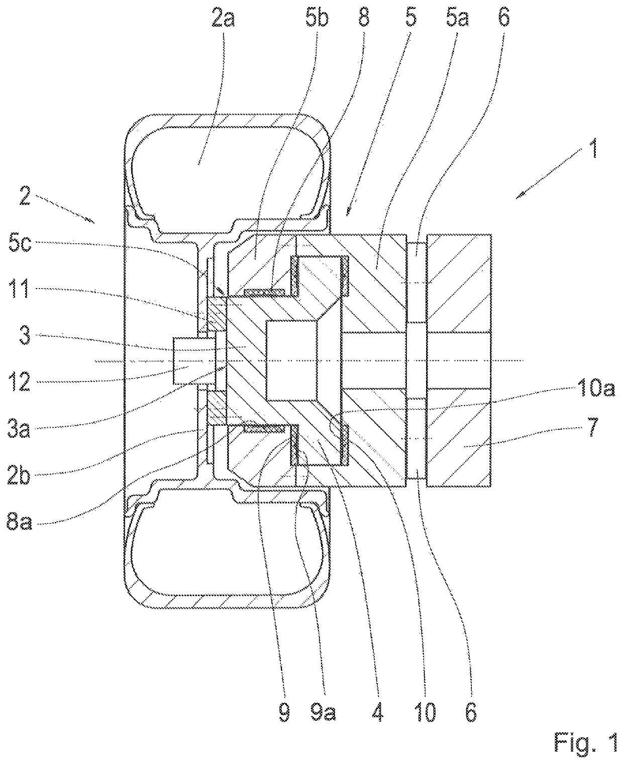
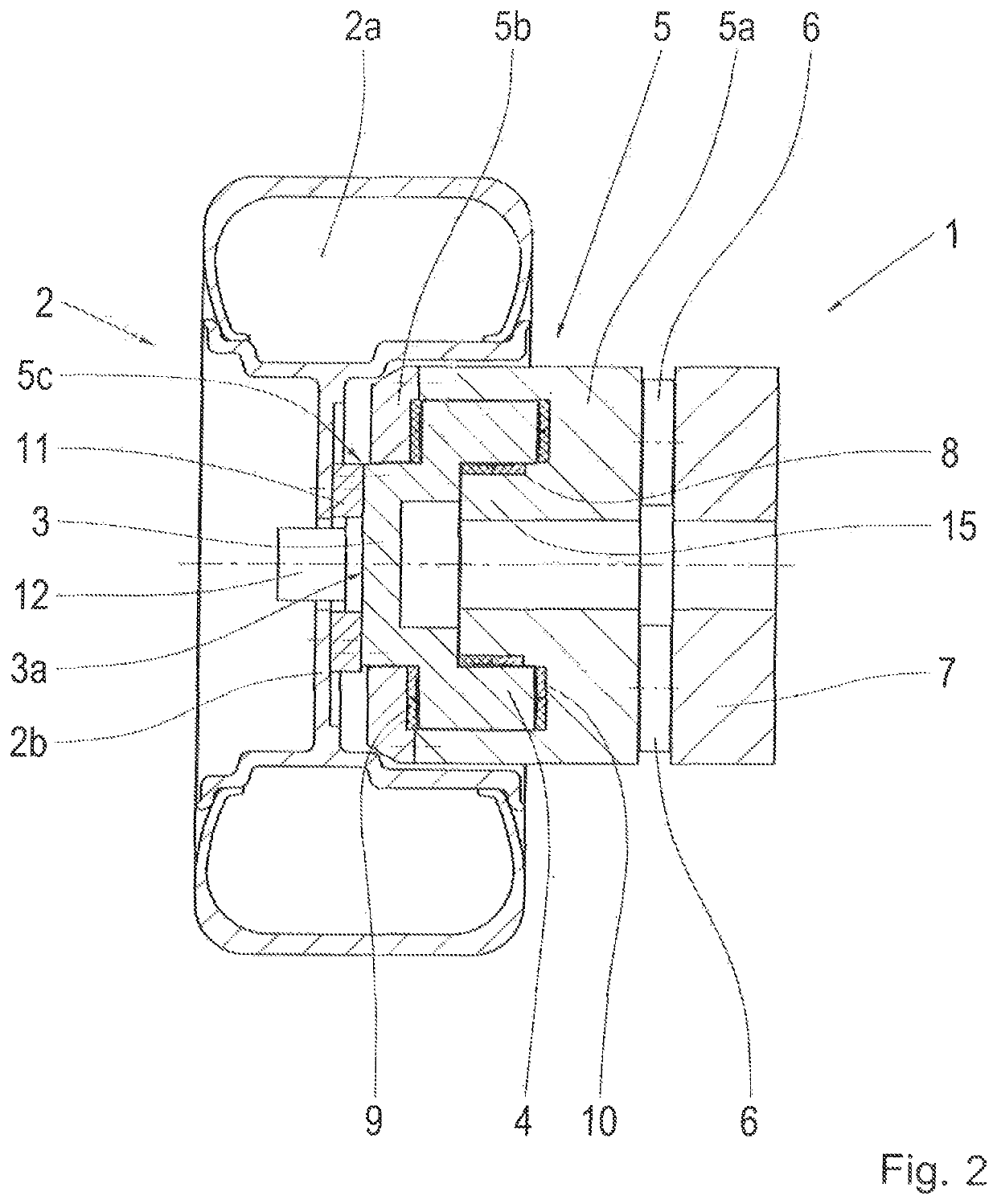
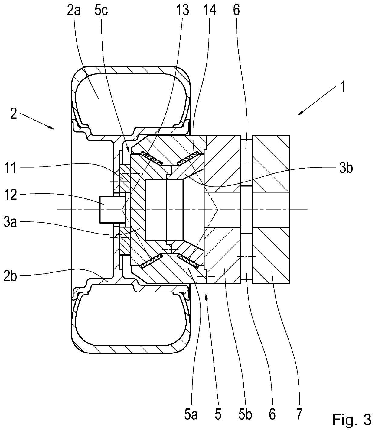
[0025]FIG. 1 shows an example embodiment of a wheel-force dynamometer 1 according to the invention with a vehicle wheel 2 arranged on it and which comprises a vehicle tire 2a and a wheel rim 2b. The wheel-force dynamometer 1 shown is designed for the measurement of forces and torques imposed upon the vehicle wheel 2 during rotation thereof. In particular, the wheel-force dynamometer 1 is designed to measure the so-termed high speed uniformity (HSU) of the vehicle wheel 2. The wheel-force dynamometer 1 shown as an example is FIG. 1 has a rotor 3 with an outer collar 4, which is mounted so that it can rotate in a rigid and positionally fixed housing 5. In this example the housing 5 consists of a housing body 5a and a housing lid 5b, and due to its geometry and material properties it is particularly rigid. The housing body 5a and the housing lid 5b hold the rotor 3 axially fixed in the housing 5. By means of force sensors 6, the housing 5 is supported by its housing body 5a on a suppor...


PUM


Abstract

A wheel-force dynamometer (1) for measuring, via force sensors (6), force and torque that act upon a vehicle tire (2a) and a vehicle wheel (2). The vehicle wheel (2) is mounted to rotate by way of a wheel axle. The wheel-force dynamometer (1) is characterized in that the wheel axle is in the form of a rotor (3) which is hydrostatically mounted, axially fixed and able to rotate in the circumferential direction, in a rigid and positionally fixed housing (5).

Description

[0001]This application is a National Stage completion of PCT / EP2016 / 076897 filed Nov. 8, 2016, which claims priority from German patent application serial no. 10 2015 224 638.8 filed Dec. 8, 2015.FIELD OF THE INVENTION[0002]The invention relates to a wheel-force dynamometer.BACKGROUND OF THE INVENTION[0003]From DE 102 60 000 B4 by the present applicant a wheel-force dynamometer for measuring tire forces is known, wherein a vehicle wheel is fixed onto a wheel axle which is mounted by roller bearings in a hollow shaft. The hollow shaft is mounted hydrostatically in a housing fixed to a frame and has a collar on which force sensors for the measurement of forces and torques are arranged. The forces acting on the wheel are thus transmitted via the wheel axle to the hollow shaft, which for its part “floats” in a frictionless manner by hydrostatic means in the housing. During the measurement of tire forces by a wheel-force dynamometer, measurement errors can occur, which are determined by ...

Claims


Application Information

Patent Timeline
Patent Type & Authority Patents(United States)
IPC IPC(8): G01M1/24
CPCG01M1/24F16C32/0696
Inventor EISENBEISS, JENSBÖSL, ROLAND
Owner ZF FRIEDRICHSHAFEN AG
Why Eureka
Try Eureka