Shoe lace lock and system and method for lacing shoes

a shoelace and lock technology, applied in the field of shoelaces, can solve the problems of tying a knot in the shoelace, affecting the lacing effect, and causing the tying knot to be frustrating or even impossible, and the task can be much more difficul

Active Publication Date: 2020-07-14
XPAND
View PDF95 Cites 1 Cited by
  • Summary
  • Abstract
  • Description
  • Claims
  • Application Information

AI Technical Summary

Problems solved by technology

Although time-honored, the traditional approach of tensioning and then tying shoelaces presents a number of drawbacks.
⋅Although simple enough for most people, the task is still tedious and frequently annoying, especially when the knots accidentally undo and the laces go loose, typically at a most inopportune time.
For many people, however, the task can present a much greater challenge.
For such individuals, the act of tying an untying a knot in a shoelace may prove frustrating or even impossible.
Furthermore, loose shoelaces commonly create a trip hazard that can lead to a fall, which can have serious consequences for anyone, but even more so for those engaged in running and other athletic activities.
Furthermore, an untied shoelace may present grave consequences if the wearer is engaged in a high risk activity, such as work in a hazardous environment (e.g., around rotating or moving equipment), climbing / working at heights, or engaged in law enforcement / firefighting activities / military activities.
Such drawbacks of tying laces in the conventional manner have not gone unnoticed.
Many have been multi-piece devices featuring moving jaws, clasps, spring-loaded plungers, cooperating pieces with openings that slide in-and-out of register, and so on: Particular drawbacks of such devices include complexity, with the associated potential for wear / failure of the moving parts and cost of manufacture, the latter of critical importance in such a small accessory.
Also, these devices commonly require the user to carefully thread the lace ends back-and-forth through the parts, and many also require the user to maintain continuous finger pressure against a spring-loaded plunger or other part while tensioning and / or releasing the laces, both of which are potentially problematic for persons having compromised finger strength or dexterity.
Even for those having ordinary finger strength, the force of the spring or other biasing member must be kept below a certain maximum, in order to be operable within the limits of a normal hand / fingers with the result that the various clamping and kinking mechanisms of such devices are frequently unable to generate sufficient grip to hold the lace ends against slipping.
While some prior devices have employed one-piece construction, many of those have still required that the laces be routed back-and-forth, in a manner that is tedious and time-consuming at best and potentially impossible for those with compromised dexterity / strength.
Furthermore, many share the problem of generating insufficient grip to prevent the lace ends slipping under tension.

Method used


Image

  • Shoe lace lock and system and method for lacing shoes
  • Shoe lace lock and system and method for lacing shoes
  • Shoe lace lock and system and method for lacing shoes

Examples


Embodiment Construction

[0028]In the following detailed description, reference is made to the accompanying drawings, which form a part hereof. In the drawings, similar reference characters typically identify similar components, unless context dictates otherwise. Other embodiments may be used and / or other changes may be made without departing from the spirit or scope of the disclosure. For ease of understanding, the terms “forward,”“front,”“rearward,”“back” and the like, as used in this description, refer respectively to the directions or relative locations proximal (towards) and distal (away) from the perspective of a user wearing a shoe or other article of footwear (i.e., the forward end is towards the ankle and the rearward end is towards the toes); similarly the terms “upper,”“top” and “lower,”“bottom” refer to the dorsal and plantar directions from the perspective of such a user.

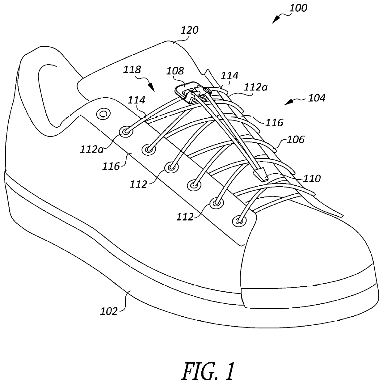
[0029]FIG. 1 is a perspective view of a shoe assembly 100, according to an embodiment, which includes a shoe 102 and a lacing...


PUM


Abstract

A cord lock device is provided, which includes a body having first and second faces, with a cord passage extending through the body between the first and second faces. First and second grip channels are formed in the first face and have respective first ends adjacent to the cord passage and second ends extending away from the cord passage. Each of the grip channels has a pair of grip teeth facing each other on opposite sides of the respective grip channel, ridges of the pairs of grip teeth extending from the first face toward the second face at an angle such that at the first face, the ridges are furthest from the cord passage, while at a point closest to the second face, the ridges are closest to the cord passage.

Description

CONTINUING INFORMATION[0001]This application claims the priority of U.S. Provisional Patent Application Ser. No. 62 / 601,184 filed Mar. 13, 2017.BACKGROUNDa. Field of the Invention[0002]The present invention relates generally to laces for shoes, boots and other articles of footwear, and, more particularly to a lock piece having first and second channels that allow the ends of an elastomeric shoelace to be drawn therethrough as a user applies tension, but that grip and hold the lace ends fast against loosening when released by the user.b. Related Art[0003]It has been common practice from time immemorial to pull on the ends of a shoelace in order to cinch a shoe or other article of footwear about the foot, and then tie the ends together to prevent the lace from loosening. As used herein, the terms “shoe” and “shoes” include shoes, boots and other articles of footwear, as well as other articles that are similarly tightened about the foot and / or limb, and the terms “lace” and “laces” inc...

Claims


Application Information

Patent Timeline
Patent Type & Authority Patents(United States)
IPC IPC(8): F16G11/00A43C1/02A43C7/00A41D3/00
CPCA43C7/00A43C1/02A41D2300/22A41D3/00
Inventor HARRIS, CHARLES DAVID
Owner XPAND
Why Eureka
Try Eureka