
Paper conveyance device, image forming apparatus, paper conveyance control method, and recording medium

a technology of paper conveyancing and image forming, which is applied in the direction of electrographic process apparatus, thin material processing, instruments, etc., can solve the problems of high friction force and an increase in the load torque of the downstream roller, the increase of the load torque of the roller driving the motor, and the increase of the load torque of the downstream roller. , to achieve the effect of minimizing the increase in the load torque of the upstream and downstream roller

Active Publication Date: 2020-07-14
KONICA MINOLTA INC
View PDF12 Cites 0 Cited by
  • Summary
  • Abstract
  • Description
  • Claims
  • Application Information

AI Technical Summary

Benefits of technology

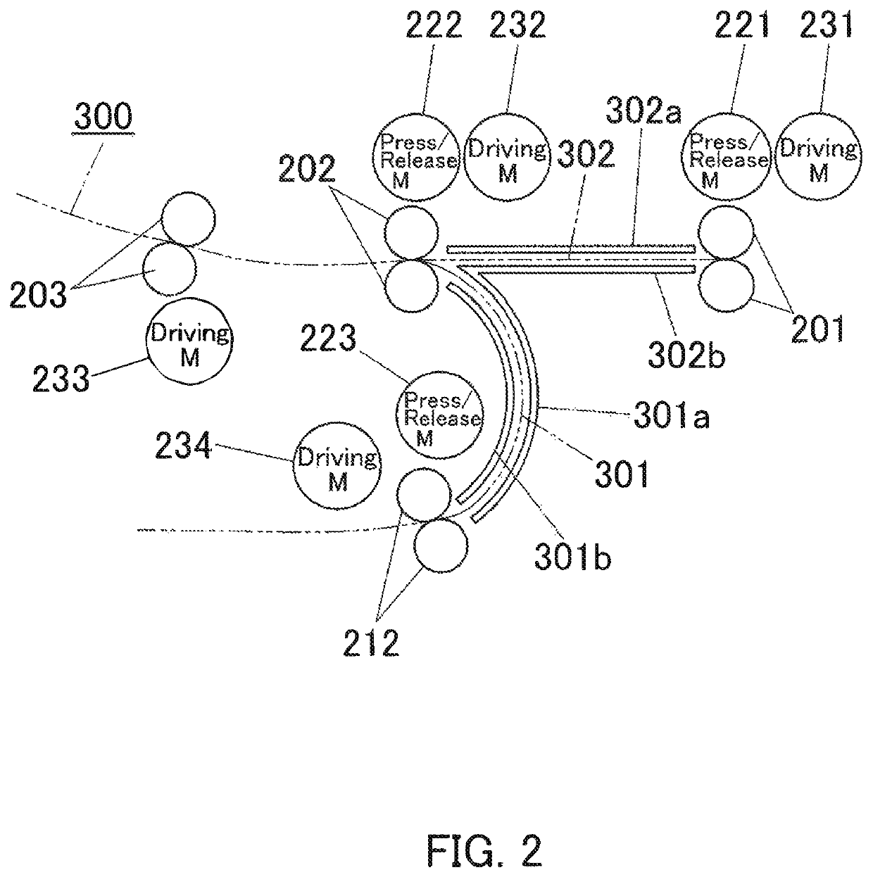
The present invention is about a device, method, and recording medium for transporting paper. It includes rollers that are placed both upstream and downstream of the paper conveyance path, and guides that help direct the paper along the path. The purpose is to reduce the strain on the rollers caused by the paper rubbing against the guides.

Problems solved by technology

So, when the downstream rollers pull the paper in during paper conveyance, the paper can rub against one of the paper conveyance guides, causing a friction torque and an increase in the load torque on the motor.
For example, when the downstream rollers pull tough paper in, the paper rubs against one of the paper conveyance guides strongly, causing a high friction force and an increase in the load torque on the downstream rollers.
Japanese Unexamined Patent Application Publication No. 2011-081347 and No. 2011-128398 do not bring a solution to the problem: the load torque on a roller driving motor increases because paper rubs against a paper conveyance guide.

Method used


Image

  • Paper conveyance device, image forming apparatus, paper conveyance control method, and recording medium
  • Paper conveyance device, image forming apparatus, paper conveyance control method, and recording medium
  • Paper conveyance device, image forming apparatus, paper conveyance control method, and recording medium

Examples


Embodiment Construction

[0046]Hereinafter, one or more embodiments of the present invention will be described with reference to the drawings. However, the scope of the invention is not limited to the disclosed embodiments.

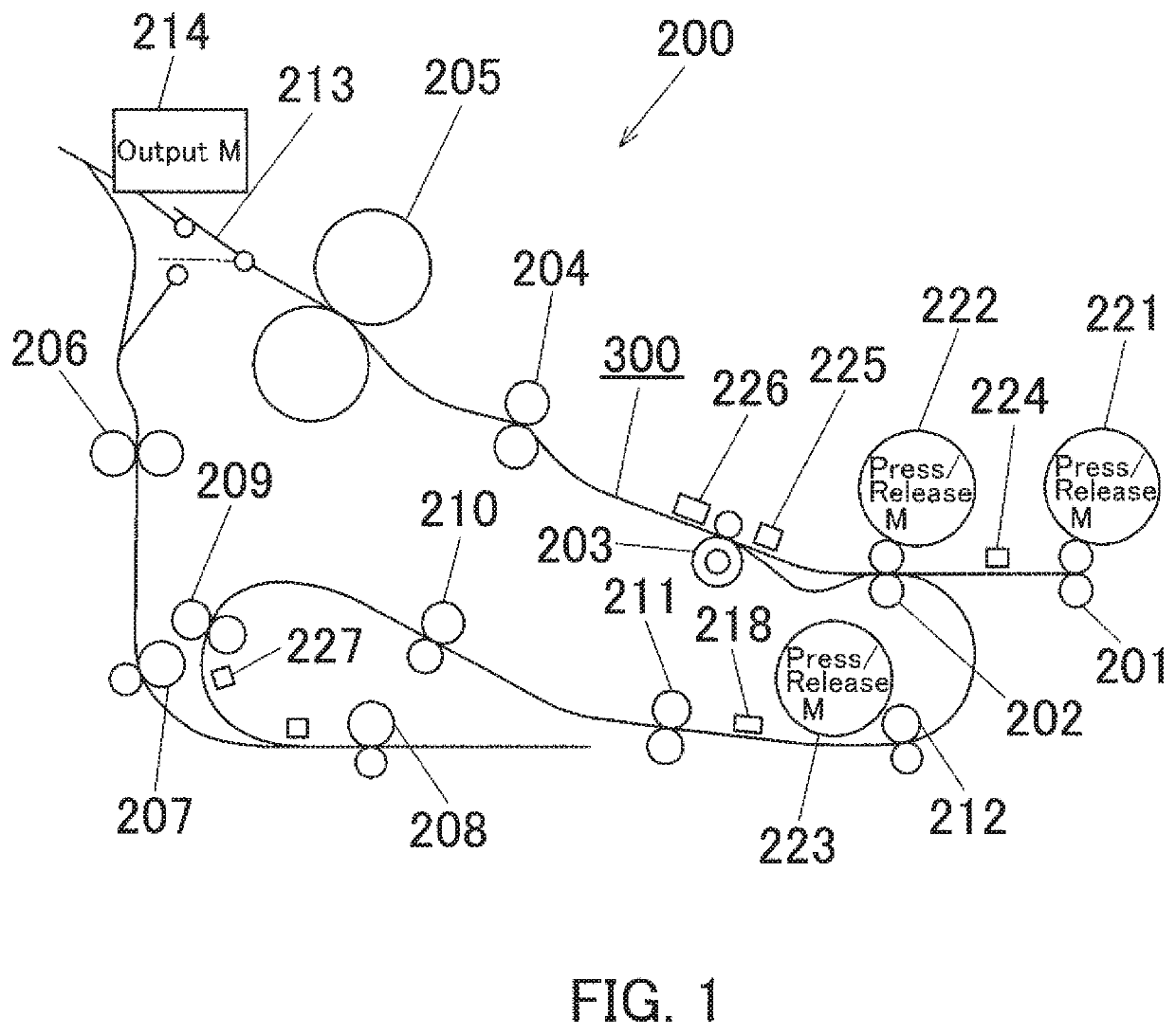
[0047]FIG. 1 is a schematic diagram illustrating a configuration of a paper conveyance section 200 of an image forming apparatus according to one embodiment of the present invention.

[0048]The image forming apparatus may be a multifunctional digital machine referred to as MFP, a printer, a copier, or a facsimile, for example.

[0049]The paper conveyance section 200 is provided with a pair of conveyance rollers 201 that conveys paper received from a paper tray (not shown in the figure). Also, the paper conveyance section 200 is provided with: a pair of bending rollers 202; a pair of paper stop rollers 203; a pair of second transfer rollers 204; and a pair of fusing rollers 205 that constitutes a fuser; and these are located in this order downstream from the conveyance rollers 201. The second ...


PUM


Abstract

A paper conveyance device includes: an upstream roller and a downstream roller being arranged at an interval in a paper conveyance path; paper conveyance guides being arranged between the upstream and downstream roller in the paper conveyance path to guide both surfaces of paper along the paper conveyance path during paper conveyance; drivers that drive the upstream and downstream roller independently; and a processor that measures the load torques on the upstream and downstream roller, that judges whether or not the paper is rubbing against one of the paper conveyance guides with reference to the load torques on the upstream and downstream roller, the load torques being obtained by the processor, and that performs controlled paper conveyance with reference to the load torques on the upstream and downstream roller depending on the result of the judgment being obtained by the processor.

Description

[0001]The disclosure of Japanese Patent Application No. 2017-235955 filed on Dec. 8, 2017, including description, claims, drawings, and abstract, is incorporated herein by reference in its entirety.BACKGROUNDTechnological Field[0002]The present invention relates to: a paper conveyance device to be loaded in an image forming apparatus, for example, and that conveys a print medium such as copy paper; an image forming apparatus provided with this paper conveyance device; a paper conveyance control method to be implemented by this paper conveyance device; and a recording medium.Description of the Related Art[0003]When copy paper is conveyed in a conventional image forming apparatus, upstream rollers release the paper as the leading edge of the paper reaches downstream rollers. By controlled paper conveyance like this, the conventional image forming apparatus achieves in reduction of the amount of power consumed by its driving motor for the upstream rollers.[0004]The conventional image f...

Claims


Application Information

Patent Timeline
Patent Type & Authority Patents(United States)
IPC IPC(8): B65H7/06G03G15/00B65H5/38B65H5/06
CPCB65H5/38B65H7/06B65H5/062G03G15/6529G03G15/55B65H2404/6111B65H2515/32B65H2513/11B65H85/00B65H2801/06B65H2220/01B65H2220/02
Inventor YAMAGUCHI, HIROSHIASANO, HITOSHIHIGASHI, TOSHIKAZUTAMURA, TOMONOBU
Owner KONICA MINOLTA INC
Learn More