
Compressor wheel assembly

A technology for compressors and compressor housings, which is applied in the direction of engine components, pump components, rotary piston type/swing piston type pump components, etc., which can solve problems such as difficult concentricity, and achieve the effect of improving the ability to carry torque

Inactive Publication Date: 2008-02-06
CUMMINS TURBO TECH
View PDF3 Cites 0 Cited by
  • Summary
  • Abstract
  • Description
  • Claims
  • Application Information

AI Technical Summary

Problems solved by technology

However, such assemblies also create balancing problems due to the threaded connection between the compressor wheel and shaft and the clearances inherent in this connection can make it difficult to maintain the desired concentricity

Method used


Image

  • Compressor wheel assembly

Examples


Embodiment Construction

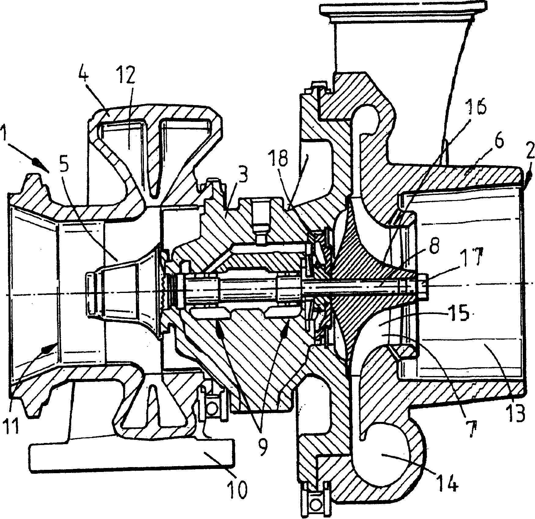
[0012] The illustrated turbocharger comprises a turbine 1 connected to a compressor 2 via a central bearing chamber 3 . The turbine 1 comprises a turbine housing 4 which accommodates a turbine wheel 5 . Similarly, the compressor 2 comprises a compressor housing 6 housing a compressor wheel 7 . The turbine wheel 5 and the compressor wheel 7 are mounted on opposite ends of a common shaft 8 which is supported by a bearing assembly 9 located in the bearing chamber 3 .

[0013] The turbine housing 4 is provided with an exhaust gas inlet 10 and an exhaust gas outlet 11 . The inlet 10 directs the incoming exhaust gases into an annular intake chamber 12 around the turbine wheel 5 . Exhaust gases flow through the turbine and flow into the exhaust outlet 11 through a circular exhaust opening coaxial with the turbine runner 5 . The rotation of the turbine wheel 5 drives the rotation of the compressor wheel 7 , which sucks in air through the axial inlet 13 and delivers the compressed a...


PUM


Abstract

A turbocharger comprises a compressor wheel (7) assembled to one end of a turbocharger shaft (8). A nut (17) is threaded on to the end of the shaft (8) to clamp the wheel (7) on the shaft to prevent both axial movement of the wheel (7) along the shaft (8) and rotational slippage. The torque capacity of the coupling between the compressor wheel (7) and nut (17) is increased by treating contacting surfaces of the coupling to increase their co-efficient of friction.

Description

technical field [0001] The present invention relates to compressor wheel assemblies mounted on shafts. More particularly, the present invention relates to a turbocharger compressor wheel assembly. Background technique [0002] It is well known that a turbocharger is a device for feeding air at a pressure above atmospheric pressure (boost) to the intake of an internal combustion engine. A conventional turbocharger basically consists of a turbine wheel driven by exhaust gases on a shaft mounted in a turbine housing. The rotation of the turbine wheel rotates the compressor wheel mounted on the other end of the shaft in the compressor housing. The compressor wheel delivers compressed air into the engine's intake manifold, thereby increasing the engine's power. The shaft is supported by radial thrust bearings connected in a central bearing chamber between the turbine and compressor wheel chambers. [0003] A conventional compressor wheel includes a set of blades extending fro...

Claims


Application Information

Patent Timeline
Patent Type & Authority Patents(China)
IPC IPC(8): F02C6/12F02B37/12F02B41/10F04C29/00F04C18/02F02B39/00B21H7/16C23F4/04F04D29/26F04D29/28
CPCF04D29/266B21H7/16
Inventor A·比林格顿
Owner CUMMINS TURBO TECH
Learn More