
Image forming apparatus

a technology of image forming apparatus and transfer unit, which is applied in the direction of electrographic process apparatus, instruments, optics, etc., can solve the problems of inadequate variation in the transfer load itself, difficulty in driving the image carrier to drive the transfer unit, and difficulty in forming images, so as to increase the load torque and reduce the average speed of the transfer unit drive motor

Active Publication Date: 2022-02-15
KONICA MINOLTA INC
View PDF7 Cites 0 Cited by
  • Summary
  • Abstract
  • Description
  • Claims
  • Application Information

AI Technical Summary

Benefits of technology

The patent is about a system that can transfer sheets from different trays without causing delays or slowing down the system. However, when there is no sheet to transfer, the system may become overloaded, causing higher power consumption and decreased speed. This can affect the image quality after a tray change.

Problems solved by technology

However, when a load is applied to the transfer unit, it is difficult for the image carrier to drive the transfer unit, and there needs to be a transfer unit driver for rotationally driving the transfer unit.
That causes a problem such as a coloring error and deterioration of the image formation accuracy.
The variation in the transfer load itself is adequately slow, and has been considered to be caused by alteration in materials of the transfer unit or the cleaning unit over time (gradual alteration of materials throughout life).
However, there is a problem in the method described above.
That may cause slippage from the intermediate transfer belt and increase the image magnification ratio of the sixth sheet after the tray change (Section B of FIG. 9D).
In that case, however, the load gets heavy due to saturation of the amount of the lubricant caused by idling while no sheet is fed for the secondary transfer.
That increases the load torque more than expected and decreases the average speed of the transfer unit drive motor, possibly affecting the image magnification ratio after the tray change.
On contrary, it is not efficient to separate the transfer unit and reobtain a drive torque for a constant speed in a continuous operation because it takes time.

Method used


Image

  • Image forming apparatus
  • Image forming apparatus
  • Image forming apparatus

Examples


Embodiment Construction

[0043]Hereinafter, an embodiment of the present invention is described with reference to the drawings. However, the scope of the invention is not limited to the disclosed embodiments.

Overview of Image Forming Apparatus

[Exemplary Configuration of Image Forming Apparatus]

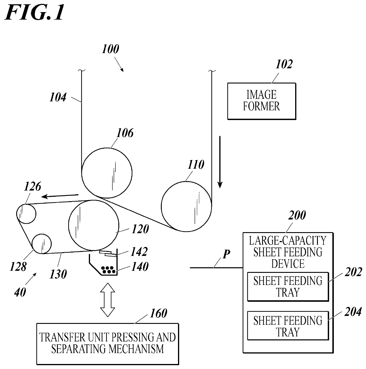
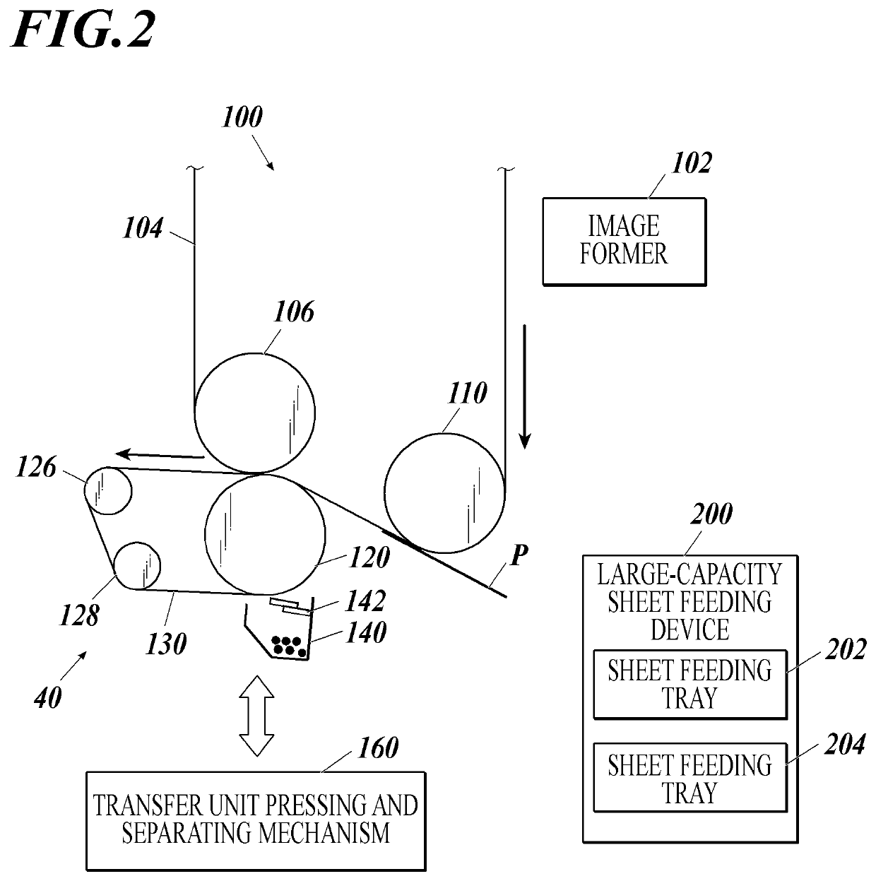
[0044]First, an exemplary configuration of an image forming apparatus 100 is described. FIG. 1 schematically shows an exemplary configuration of a transfer unit in a separated state of the image forming apparatus 100, and FIG. 2 schematically shows an exemplary configuration of the transfer unit in a pressed state of the image forming apparatus 100. The dimensional ratios of the drawings are expanded for convenience of explanation, and may be different from the actual ratios.

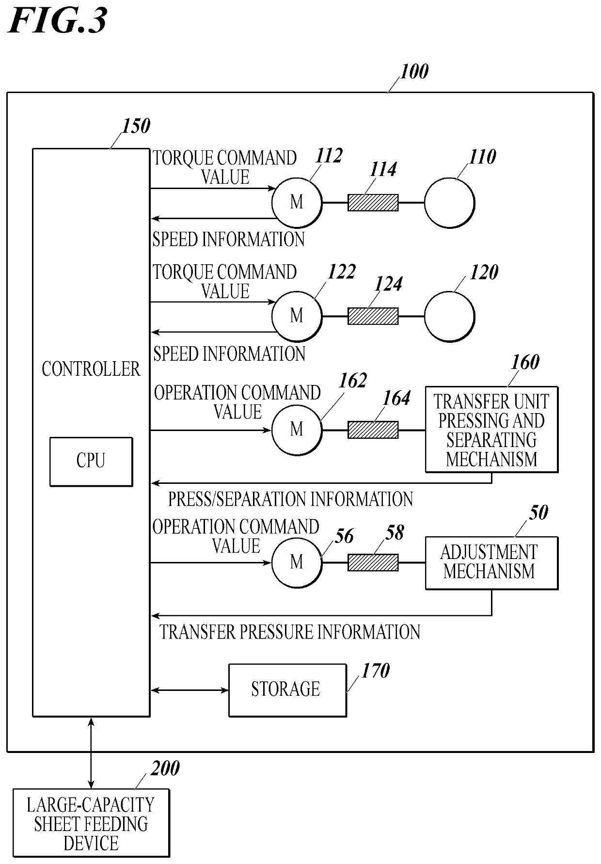
[0045]As shown in FIGS. 1 and 2, the image forming apparatus 100 includes an image former 102, an intermediate transfer belt 104, an image carrier drive roller 110, an image carrier driven roller 106, a transfer roller 120, a transfer unit drive ...


PUM


Abstract

Provided is an image forming apparatus including an image carrier, a transfer unit, a driver, a hardware processor, an adjustment mechanism, and a speed detector. The hardware processor sets a command value. The hardware processor performs a constant-torque control based on a constant-speed drive torque detected in a constant-speed control. In the constant-torque control, the hardware processor performs a feedback control to set a reference value to an average speed of the driver during passage of a first sheet and calculate a difference from an average speed during passage of a subsequent sheet so as to derive the command value. The hardware processor determines whether a load torque increase, its factor, and / or its influence exceeds a threshold, and forcibly sets the reference value to a speed detected while a pressure between the transfer unit and the image carrier is reduced by the adjustment mechanism from the pressure during image transfer.

Description

CROSS-REFERENCE TO RELATED APPLICATIONS[0001]The entire disclosure of Japanese Patent Application No. 2020-066395 filed on Apr. 2, 2020 is incorporated herein by reference in its entirety.BACKGROUNDTechnological Field[0002]The present invention relates to an image forming apparatus that presses a transfer unit against an image carrier with a toner image, feeds a paper sheet between the image carrier and the transfer unit pressed against each other, and thereby transfers the toner image onto the image carrier.Description of the Related Art[0003]Image forming apparatuses with functions of a printer, facsimile, copier, MFP, etc. are widespread in recent years. In such image forming apparatuses, a latent image is formed on a photoreceptor based on image data and developed with developing materials, and is transferred onto a paper sheet directly or via an intermediate transfer unit. A transfer unit composed of a transfer roller, a transfer belt, etc. is pressed against an image carrier c...

Claims


Application Information

Patent Timeline
Patent Type & Authority Patents(United States)
IPC IPC(8): G03G15/16G03G15/00
CPCG03G15/161G03G15/505G03G15/5008G03G15/6555G03G15/1615G03G15/167G03G2215/00949G03G15/6564
Inventor OGURA, KEIGOSUGAYA, NAOTOYAMAGUCHI, HIROSHIISHIZUKA, TATSUO
Owner KONICA MINOLTA INC
Learn More