Transportable container, charger system, method and kit for generation of carbon dioxide snow block in-situ within the transportable container for preservation of items stored therewithin

a technology of carbon dioxide snow block and transportable container, which is applied in the field of unique equipment, charger system, method and kit for insitu generation of carbon dioxide, can solve the problems of dry ice to lose its cooling effect, the clinical site cannot maintain a sufficient supply of dry ice, and the laborious assembly of the insulated box and the loading of dry ice,

Active Publication Date: 2020-07-14
PRAXAIR TECH INC
View PDF42 Cites 1 Cited by
  • Summary
  • Abstract
  • Description
  • Claims
  • Application Information

AI Technical Summary

Benefits of technology

[0012]In a fourth aspect, A carbon dioxide (CO2) snow charger system adapted to produce CO2 snow block, comprising: a meshed conduit, said meshed conduit comprising porous openings sufficient for CO2 off-gas to pass through the openings into an internal passageway of the meshed conduit, but substantially block entry of particles from the CO2 snow block into the internal passageway, said meshed conduit characterized by sufficient rigidity to pack the CO2 snow block generated external to the meshed conduit; and a CO2 snow charger operably or integrally connected to the meshed conduit, said CO2 snow charger comprising a conduit network with a plurality of nozzles, the plurality of nozzles configured to selectively direct CO2 fluid external to the meshed conduit while substantially avoiding introduction of CO2 liquid into the internal passageway of the meshed conduit, the snow charger further comprising one or more exhaust openings in fluid communication with the internal passageway of the meshed conduit, said one or more exhaust openings configured to allow gas to vent therethrough.
[0014]In a sixth aspect, a method for assembling a carbon dioxide (CO2) snow charging system at a site for in-situ generation of CO2 snow block in a container, comprising: providing a CO2 source; providing an insulated container with an opening, the container further comprising an interior volume defined into a first region and a second region, wherein the first region is an internal meshed conduit volume, and the second region is a snow chamber; providing a meshed conduit operably connected or integrally connected to the insulated container; providing a CO2 snow charger comprising a conduit network having an inlet opening to receive the CO2 source and a plurality of nozzles distributed along an edge of the conduit, said CO2 snow charger further comprising one or more exhaust openings for gas to exhaust therefrom; attaching the CO2 snow charger to the container; securing a top of the meshed conduit to the CO2 snow charger at the top opening of the container; and operably connecting the inlet opening of the CO2 snow charger to the CO2 source.

Problems solved by technology

Assembly of the insulated box and loading of the dry ice can be labor intensive.
There may also be considerable cost and inconvenience associated with maintaining a sufficient supply of dry ice at the clinical site.
Additionally, the failure to use such dry ice within a certain duration can cause the dry ice to lose its cooling effect.
Further, the insulated box is typically not reusable and must be discarded, thereby creating waste.
Other drawbacks also exist with the transport of samples in conventional insulated boxes.
The interior sample space may be uniformly near dry ice temperature upon initial full dry ice loading, but as the dry ice sublimates, significant temperature gradients can arise within the interior sample space, potentially compromising sample quality.
However, should delays or disruptions occur in the shipping lanes, the samples can degrade.
As a result of such delays during shipment, additional dry ice may be required to be loaded into the box during transit, which results in increased cost and logistical complexity to the shipment.
However, such liquid nitrogen-based vapor vessels suffer from drawbacks.
One drawback is the time and labor involved in the preparation of the vessel.
Substantial handling of the cryogenic liquid nitrogen is necessary, and significant time is required to prepare the liquid nitrogen shipper prior to its usage.
Further, the costs associated with the use of liquid nitrogen-based vapor vessels are significantly higher than alternative dry ice vessels.

Method used


Image

  • Transportable container, charger system, method and kit for generation of carbon dioxide snow block in-situ within the transportable container for preservation of items stored therewithin
  • Transportable container, charger system, method and kit for generation of carbon dioxide snow block in-situ within the transportable container for preservation of items stored therewithin
  • Transportable container, charger system, method and kit for generation of carbon dioxide snow block in-situ within the transportable container for preservation of items stored therewithin

Examples


example 1 (

Invention)

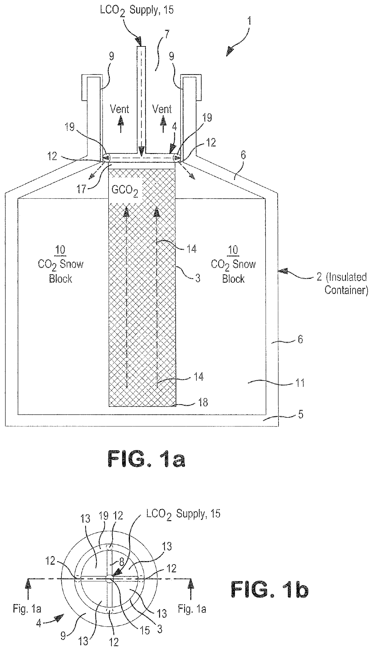
[0102]In accordance with the principles of the present invention, a prototype kit as shown in FIG. 1a was fabricated and assembled to generate CO2 snow block. A cylindrical meshed tube was inserted and installed into the interior of a substantially cylindrical container. The container had an overall height of 19.4 inches (defined as the height spanning from the bottommost portion of the container 2 to the topmost portion of the container 2), a neck diameter of 3.58 inches and an overall diameter of 9.2 inches (defined as the widest portion of the container 2 from sidewall to sidewall). The total interior storage volume was about 6 liters with a top cover secured to the top of the container. The cylindrical meshed tube had a volume of about 1 liter.

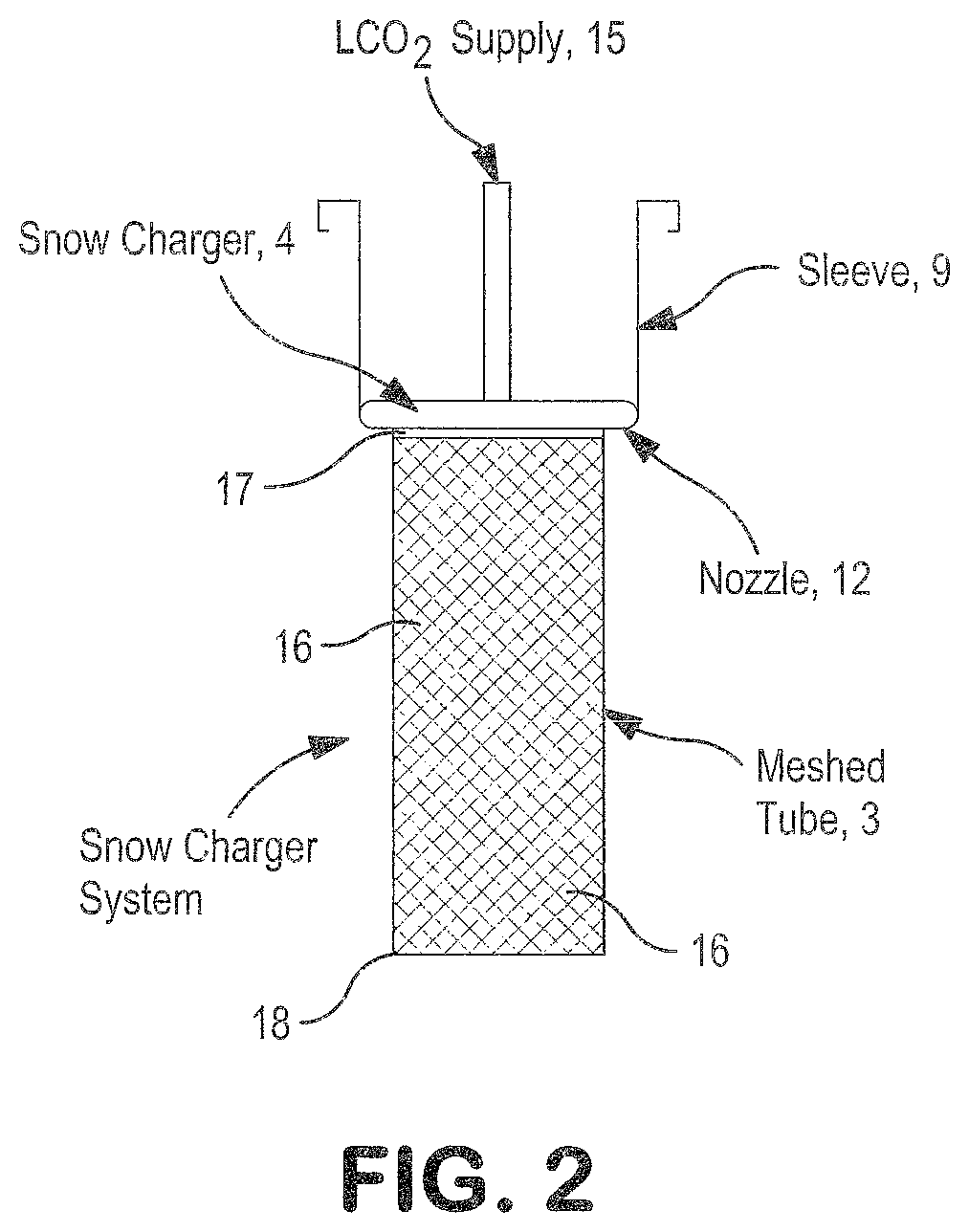
[0103]A snow charger including a circular flow conduit network with multiple nozzles arranged along the periphery of the circular flow conduit network was connected to the top portion of the mesh tube. The central opening of the ...

example 2 (

Invention)

[0108]The temperature profile of the inventive prototype with CO2 snow block produced therein as described in Example 1 was evaluated and then compared with the temperature profile of the CO2 dry ice pellets contained in the standard shipper evaluated as described in Comparative Example 1.

[0109]The meshed tube and snow charger were removed from the container of the prototype kit. Thermocouples were then placed slightly below the bottom of the cover for the container. A top cover was placed onto the opening of the container.

[0110]Temperature measurements were obtained for almost 96 hours. The results indicated the prototype container with the CO2 snow block in-situ generated therein approached a temperature no warmer than −60° C. over 90 hrs. The results are shown in FIG. 8. The temperature at a given time represents an average of the temperature measurements obtained from the different thermocouples situated in the container. The temperature profile of the inventive protot...

example 3 (

Invention)

[0111]The effect of different R values on the performance of the prototype kit of the present invention was evaluated. As known in the art, the R value is measure of thermal resistance that is employed to quantify endurance, which is an indicator of the duration a certain item can be maintained within the container at a temperature no warmer than a certain pre-defined temperature. In the tests carried out herein, the pre-defined temperature not to exceed was −60° C. The same container as employed in Example 1 and Example 2 were used to carry out the tests. The container as manufactured initially was vacuum jacketed to a level of 1000 microns. The container included a vacuum port that allowed access to the vacuum insulated walls. A vacuum device was connected as necessary to the vacuum port to achieve different vacuum levels to evaluate the endurance.

[0112]In the first test, the endurance of the container at a vacuum insulated jacket of approximately 1000 microns was evalua...


PUM


Abstract

This invention relates to a novel kit, transportable apparatus and method for generating in-situ CO2 snow block within the apparatus. An item such as a biological sample can be stored and transported within the same apparatus that is employed for creating the CO2 snow block. The apparatus is capable of preserving the sample during transport. The invention also includes a specially designed CO2 snow charger system including a charger and meshed conduit. The charger system is operated in accordance with the methods of the present invention to create the in-situ CO2 snow block within a container that can be also used for transport.

Description

RELATED APPLICATIONS[0001]The present application claims priority from U.S. Provisional Application Ser. No. 62 / 360,760, filed Jul. 11, 2016, which is incorporated by reference herein in its entirety.FIELD OF INVENTION[0002]This invention relates to a unique apparatus, charger system, method and kit for in-situ generation of carbon dioxide (hereinafter referred to as “CO2”) snow in block form within a container that can be used for preservation and transport of various items, including biological specimens.BACKGROUND OF THE INVENTION[0003]Drug development continues to be a major endeavor in the pharmaceutical industry. Drug development requires clinical trials to establish the safety and efficacy of new treatments. Today, in the United States, alone, there are a large number of on-going clinical trials in various stages. Each clinical trial can involve hundreds to thousands of patients who have volunteered to the administering of certain experimental drugs. Generally speaking, as pa...

Claims


Application Information

Patent Timeline
Patent Type & Authority Patents(United States)
IPC IPC(8): F25D3/14F25D3/12B65D81/18A01N1/02
CPCF25D3/14F25D3/125A01N1/0257B65D81/18F25D2700/14F25D2700/123F25D2331/804F25D2700/122F25C2700/02F25D2700/02F25D3/12
Inventor ZHOU, YINGBURSAC, RANKOSEVER, ROBERT R
Owner PRAXAIR TECH INC
Why Eureka
Try Eureka