Precision transformer for antenna elements

a technology of precision transformers and antenna elements, applied in the direction of fixed transformers, magnetic cores of transformers/inductances, inductances, etc., can solve the problem that the transformer itself can become a source of unwanted interferen

Active Publication Date: 2020-07-14
RAYTHEON CO
View PDF8 Cites 13 Cited by
  • Summary
  • Abstract
  • Description
  • Claims
  • Application Information

AI Technical Summary

Problems solved by technology

Unfortunately, however, the transformer itself can become a source of unwanted interference, particularly in precisely balanced antennas.

Method used


Image

  • Precision transformer for antenna elements
  • Precision transformer for antenna elements
  • Precision transformer for antenna elements

Examples


Embodiment Construction

[0020]Aspects and embodiments are directed to the use of two anti-symmetrically wound transformers to compensate for stray radiation in antenna structures.

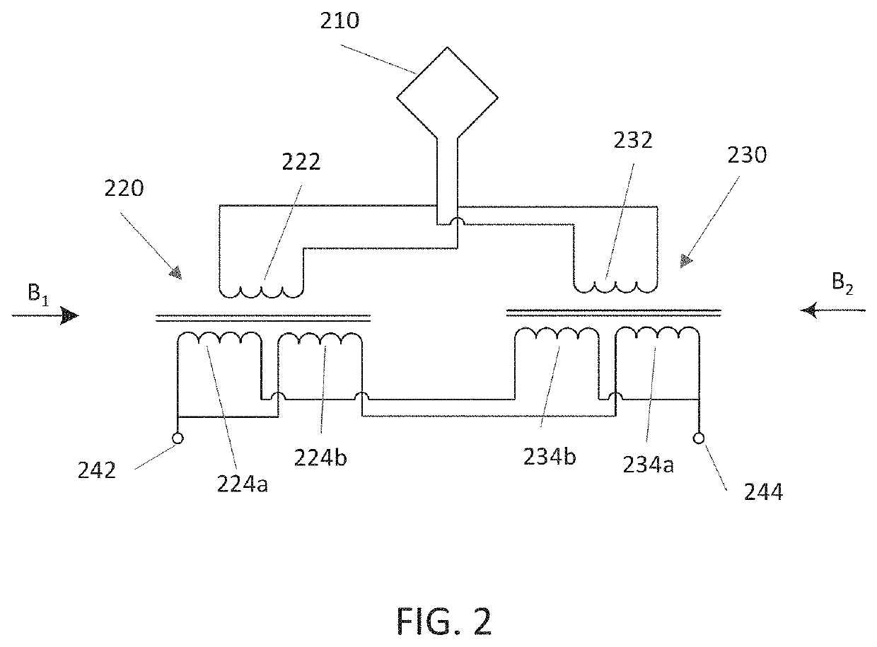
[0021]Referring to FIG. 2, there is illustrated an example of an antenna sub-system according to certain embodiments. In this example, the antenna sub-system 200 includes an antenna 210 connected to a transformer assembly including two identical (or substantially identical, meaning as identical as feasible) transformers 220, 230. Each transformer 220, 230, includes two electrically separate windings that generally are made of wire coils wound around the transformer's core. The core may be made of a magnetic or ferro-magnetic material, for example, such as laminated iron, iron powder, or ferrite. In one example, the two transformers 220, 230 are toroidal core transformers. Toroidal core transformers may be advantageous in that a toroidal transformer may be more compact than transformers with other shaped cores, and because the toro...


PUM

PropertyMeasurementUnit
ferro-magneticaaaaaaaaaa
self-shieldingaaaaaaaaaa
structureaaaaaaaaaa

Abstract

Antenna structures including two anti-symmetrically wound transformers to compensate for stray radiation. In one example an antenna structure includes a transformer assembly connected between an antenna and first and second balanced signal contacts, the transformer assembly including first and second transformer cores independently positionable in space relative to one another, a pair of primary windings connected to the antenna in parallel with one another, and a pair of balanced secondary windings connected in parallel with one another between the first and second balanced signal contacts.

Description

CROSS-REFERENCE TO RELATED APPLICATIONS[0001]This application claims the benefit under 35 U.S.C. § 119(e) of U.S. Provisional Application No. 62 / 490,369 filed on Apr. 26, 2017 and titled “PRECISION TRANSFORMER FOR ANTENNA ELEMENTS,” which is herein incorporated by reference in its entirety for all purposes.FEDERALLY SPONSORED RESEARCH[0002]This invention was made with government support under Contract No. W911QY-17-C-0003 awarded by the Department of Defense. The U.S. government has certain rights in this invention.BACKGROUND[0003]Transformers are often used as part of antenna structures. FIG. 1A is a diagram illustrating an example of a conventional antenna sub-system 100 including a transformer 110 connected to an antenna 120.[0004]A common type of transformer used in antenna structures is the BALUN transformer. An example of a BALUN transformer 110 connected to the antenna 120 is shown in FIG. 1B. The transformer includes two electrically separate windings 112, 114 that generally...

Claims


Application Information

Patent Timeline
Patent Type & Authority Patents(United States)
IPC IPC(8): H01F27/24H01Q1/50H01F19/00H01F27/38H01F27/34H03H7/42H01F27/28H01F38/00
CPCH01F27/2895H01F27/28H01F27/24H03H7/42H01F19/00H01Q1/50H01F27/346H01F27/38H01F2038/006
Inventor DOLGIN, BENJAMIN P.LAVEDAS, THOMASFRAUNDORFER, JOSEPH J.
Owner RAYTHEON CO
Why Eureka
Try Eureka