
Switch device structure

a switch device and structure technology, applied in the direction of contact mechanism, electrical apparatus, fixed to substrate, etc., can solve the problems of complex structures, bending and punching operation of the first and second leaf springs, and the loss of the emergent brake function of the switch device, so as to improve the shortcoming of the conventional switch devi

Active Publication Date: 2020-07-14
SWITCHLAB +1
View PDF5 Cites 4 Cited by
  • Summary
  • Abstract
  • Description
  • Claims
  • Application Information

AI Technical Summary

Benefits of technology

The present invention provides a switch device structure that improves the shortcoming of conventional switch devices by ensuring that the circuit can be securely opened. The switch device structure includes a main body and an operation button assembled with the main body. The main body defines a chamber in which a base seat is assembled. An operation body and a wire connection module are disposed on the base seat. The base seat is formed with a cavity in which an elastic unit is mounted. The elastic unit includes a fixed section and a free section. In response to the move of the operation body and with the fixed section serving as a fulcrum, the free section of the elastic unit can push a second contact of the wire connection module into contact with a first contact to close the circuit or away from the first contact to open the circuit.

Problems solved by technology

The conventional switch device has numerous components and relatively complicated structure so that the manufacturing and assembling cost of the conventional switch device is higher.
1. In some operation and application conditions, due to long-term use or human factors, the switch case, the operation button or the connection seat is often damaged or broken. According to the structure of the compression springs disposed between the case and the connection seat of the conventional switch device, the compression springs will lose the operation support point or load section for compressing the compression springs or releasing the energy. As a result, the compression springs will fail to truly push the connection seat so that the circuit of the wire connection module cannot be opened. In this case, the switch device will lose its emergent brakeage function and cannot emergently open the circuit.
2. In the conventional switch device, according to the structure of the first and second leaf springs in cooperation with the finger-like members disposed on the base seat (and / or assembled with the spiral springs), the first and second leaf springs must be designed with a specific structure so as to provide elastic action force. For example, one end of the first leaf spring is formed with a bent section and a movable contact. The back face of the movable contact is connected with the second leaf spring in reverse direction. The second leaf spring is formed with a U-shaped body structure including a bent section and a movable plate extending in a direction to the first leaf spring in adaptation to the finger-like member.
As well known by those who are skilled in this field, the structures and the bending and punching operation of the first and second leaf springs are complicated.
This is unbeneficial to lowering the manufacturing cost.
In structure and actual operation and application, the conventional switch device has another problem that in order to increase the elastic action force or motional range of the first and second leaf springs, the first leaf spring is especially made of a thinner band-like plate and formed with a hollow section structure.
However, such structural form will lower the electro-conductive performance of the first leaf spring.
1. The structural form of the conventional switch device that the compression springs are disposed between the case and the connection seat must be eliminated. In this case, the shortcoming of the conventional switch device that the structure of the switch device is often damaged or broken so that the compression springs assembled with the wire connection module cannot open the circuit can be improved.
2. The complicated structural form of the first and second leaf springs of the conventional switch device should be eliminated or solved. In this case, the shortcoming of the conventional switch device that in order to provide the elastic effect, the electro-conductive performance of the first leaf spring is lowered can be improved.

Method used


Image

  • Switch device structure
  • Switch device structure
  • Switch device structure

Examples


Embodiment Construction

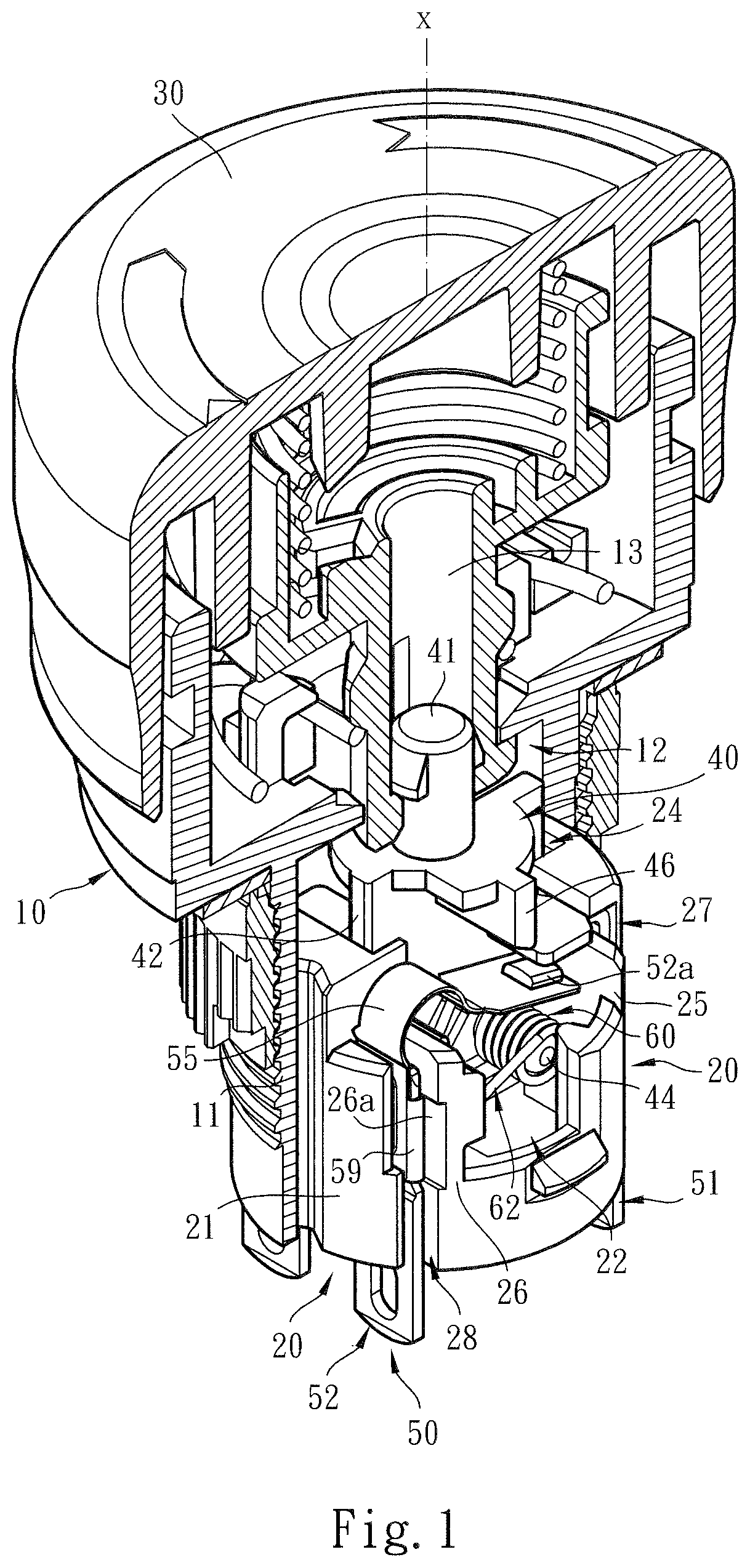
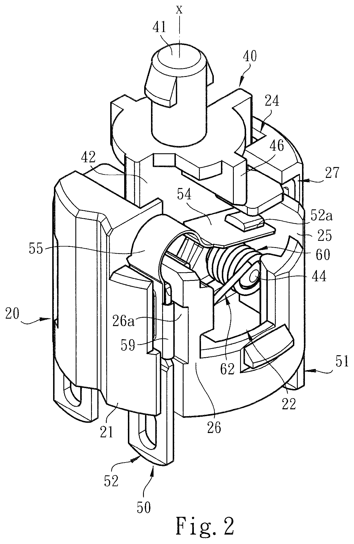
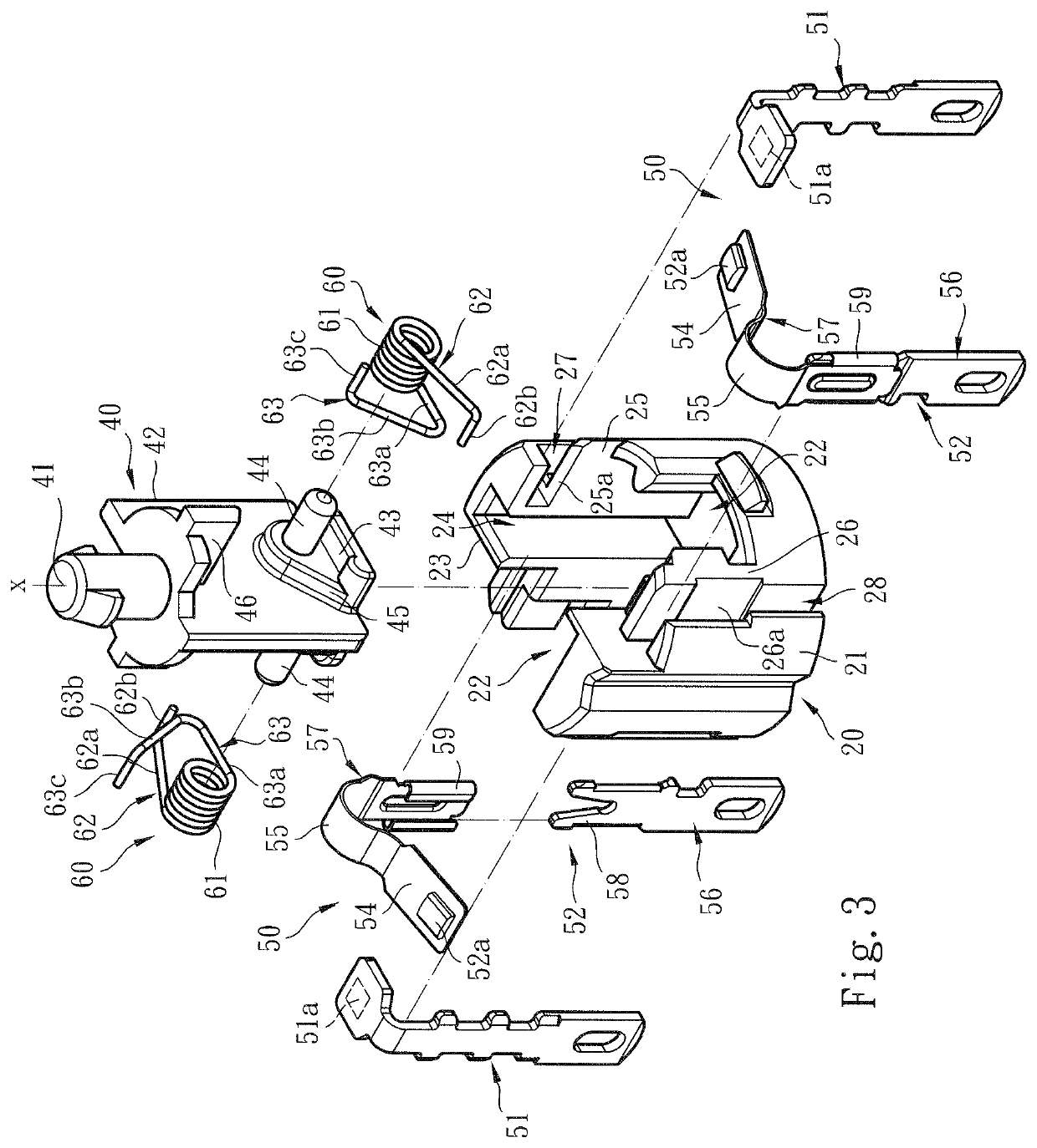
[0021]Please refer to FIGS. 1, 2 and 3. The switch device structure of the present invention includes a main body 10 and a base seat 20 assembled with the main body 10. The main body 10 is a cylindrical body structure having a base section 11. The main body 10 is defined with an axial reference axis X. An operation (push) button 30 is disposed in the main body 10. The operation button 30 is permitted to freely move and / or rotate within the main body 10 along the axial reference axis X. The relevant cooperative structures of the main body 10 and the operation button 30 pertain to prior art and thus will not be specifically described hereinafter.

[0022]In a preferred embodiment, the main body 10 (and / or the base section 11) defines a chamber 12 in which the base seat 20 and an operation body 40 are assembled. To speak specifically, the base seat 20 is a substantially cylindrical body structure having a wall 21 and at least one cavity 22 for assembling with the operation body 40 and an ...


PUM


Abstract

A switch device structure provides an ensuring system to improve the shortcoming of the conventional switch device. The switch device structure includes a main body and an operation button assembled with the main body. The main body defines a chamber in which a base seat is assembled. An operation body and a wire connection module are disposed on the base seat. The base seat is formed with a cavity in which an elastic unit is mounted. The elastic unit includes a fixed section and a free section. In response to the move of the operation body and with the fixed section serving as a fulcrum, the free section of the elastic unit can push a second contact of the wire connection module into contact with a first contact to close the circuit or away from the first contact to open the circuit.

Description

BACKGROUND OF THE INVENTION1. Field of the Invention[0001]The present invention relates generally to an improved switch device structure, and more particularly to a switch device structure including a main body and a base seat assembled with the main body. An elastic unit is mounted on the base seat to ensure that the circuit is closed and / or opened by the switch device.2. Description of the Related Art[0002]A conventional switch device is applied to an electrical, electronic and automatic control system for an operator to operate the machine or power on / off the system. Such switch device also can serve as an emergency switch. In the case that an operator improperly operates the machine or the equipment fails or the like, the operator can emergently open the circuit to power off the system so as to avoid serious damage or loss.[0003]The conventional emergency switch device generally includes an operation button equipped with a pushbutton and / or rotary switch and a case for receiving...

Claims


Application Information

Patent Timeline
Patent Type & Authority Patents(United States)
IPC IPC(8): H01H3/10H01H13/14H01H3/02H01H13/10H01H13/50
CPCH01H13/50H01H13/14H01H3/022H01H13/10H01H2003/0246H01H2235/018H01H2205/004H01H13/26
Inventor WU, CHIH-YUANHSIAO, CHIH KUN
Owner SWITCHLAB
Learn More