
Pre-matched coaxial transistor test fixture

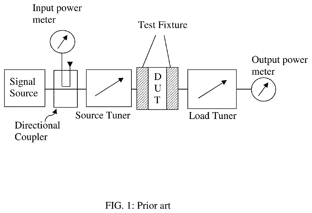
a coaxial transistor and test fixture technology, applied in the field of test fixtures, can solve the problems of extremely low loss test fixtures and reduced tuning range of tuners, and achieve the effects of low input and output internal impedance, reduced inherent tuning range of tuners, and non-negligible insertion loss

Active Publication Date: 2020-07-28
TSIRONIS CHRISTOS
View PDF5 Cites 2 Cited by
  • Summary
  • Abstract
  • Description
  • Claims
  • Application Information

AI Technical Summary

Benefits of technology

This patent text describes a new coaxial fixture that is designed to match the low impedance of high power transistors. The fixture uses airlines instead of micro-strips, which have non-negligible insertion loss. The airlines have a characteristic impedance that is different from 50 ohms to match the impedance of the transistor. By widening or narrowing the center conductor, the fixture can achieve lower or higher transmission lines, respectively. The technical effect of this new fixture is better accuracy and less loss during load pull testing of high power transistors. Additionally, the use of airlines eliminates the need for a negligible insertion loss test fixture.

Problems solved by technology

However the inherent tuning range of the tuners is reduced by the insertion loss of the test fixture; therefore there is requirement for extremely low loss test fixtures.

Method used


Image

  • Pre-matched coaxial transistor test fixture
  • Pre-matched coaxial transistor test fixture
  • Pre-matched coaxial transistor test fixture

Examples


Embodiment Construction

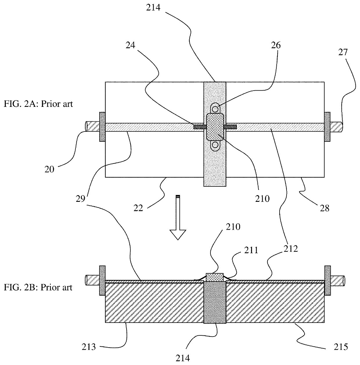
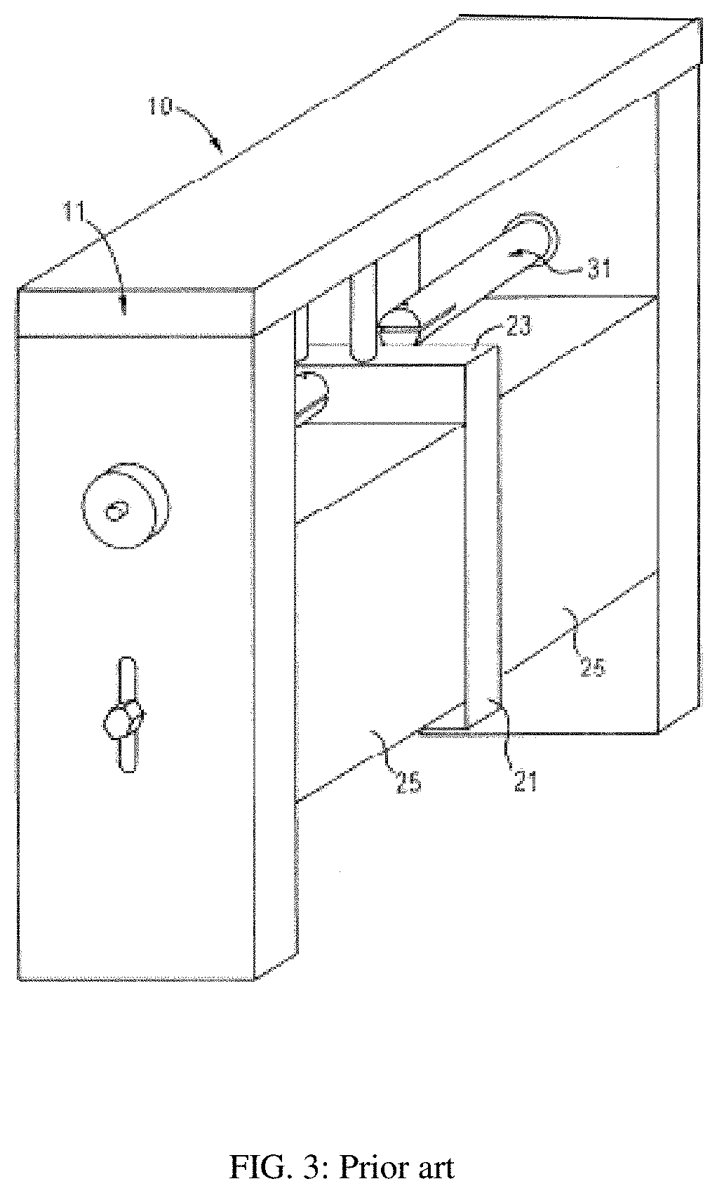
[0030]FIGS. 3 and 4 show the prior art coaxial transistor test fixture (see ref. 1). Two coaxial connectors (40, 42) are attached to vertical walls (412, 413) and the extensions of the center conductors (31, 47, 48) form with the two blocks (25, 414, 415) and the cover (11, 416) an open transmission line (slabline), which is interrupted in the center to INSERT a block (21, 44), referred hitherto as “insert”, which carries the packaged DUT (43). In this case the transistor package (43) is placed on the INSERT (44) which is part of the horizontal slabline structure formed of the bottom ground planes (49, 412, 413) and the top ground planes (46, 416) in FIGS. 4A and 4B and the center conductor (47, 48). The signal enters in the input port (40), leaves at the output port (42) and is being conducted to and from the transistor DUT by the two coaxial center conductor segments (47, 48). The transistor leads (41) are inserted into horizontal slots (411) of the center conductor segments facin...


PUM


Abstract

Coaxial microwave transistor test fixtures provide lowest insertion loss possible and include, as part of the input and output sections, transformer networks either in form of single stage λ / 4 segments, or, for larger bandwidth, multiple step segments or ramped transitions from 50Ω to the impedance closer to the internal impedance of the power transistor. The transforming networks are flat or cylindrical and can be made exchangeable in order to accommodate various transforming ratios using the same fixture body and coaxial adapters. The fixtures can be calibrated using standard TRL method.

Description

PRIORITY CLAIM[0001]This application claims priority on provisional application 62 / 436,126, titled: Pre-Matched Coaxial Transistor Test Fixture, filed on Dec. 19, 2016.CROSS-REFERENCE TO RELATED ARTICLES[0002]1. TSIRONIS, U.S. Pat. No. 6,414,563, “Low-Loss Microwave Device Test Fixture with Adjustable Blocks”[0003]2. “Test Fixture for Medium and High Power RF Transistors”, Product Note 7, Focus Microwaves, January 1994[0004]3. “Load Pull”, [online], Wikipedia [Retrieved on Nov. 18, 2016] Retrieved from Internet <URL: http: / / en.wikipedia.org / wiki / Load_pull>.[0005]4. “GaN RF Power Transistor” QPD2795 Data sheet, [online], Triquint / Qorvo, [Retrieved on Dec. 7, 2016] Retrieved from Internet <URL: http: / / www.qorvo.com / products / p / QPD2795>.[0006]5. “Lecture 22: Measurement Errors. TRL Calibration of a VNA”, K. W. Whites, EE 481 / 581, course syllabus, South Dakota School of Mines and Technology.[0007]6. “Tapered lines, notes”, Jim Stiles, University of Kansas, Dept. of EECS, Apr....

Claims


Application Information

Patent Timeline
Patent Type & Authority Patents(United States)
IPC IPC(8): G01R31/28
CPCG01R31/2822G01R1/0408G01R1/0416
Inventor TSIRONIS, CHRISTOS
Owner TSIRONIS CHRISTOS
Learn More