
Custom multiwell plate design for rapid assembly of photo-patterned hydrogels

a multi-well plate, photo-patterned technology, applied in the field of biomaterial platforms, can solve the problems of time-consuming, labor-intensive, and technical challenges, and achieve the effects of wide range of stiffness, wide and significant impact, and rapid assembly of photo-patterned hydrogels

Active Publication Date: 2020-07-28
SAINT LOUIS UNIVERSITY
View PDF9 Cites 0 Cited by
  • Summary
  • Abstract
  • Description
  • Claims
  • Application Information

AI Technical Summary

Benefits of technology

[0012]In accordance with the present disclosure, devices and methods have been discovered that surprisingly allow for the rapid assembly of photo-patterned photopolymerizable hydrogels in multiwell plate formats. The methods of the present disclosure have a broad and significant impact, as they allow for the preparation of biomaterial platforms that exhibit a wide range of stiffness and are available in a semi-high-throughput format such as a multiwell plate that are useful for elucidating cell-substrate relationships. Such devices can have an immediate impact in research areas such as, for example, drug screening, where high-throughput is a critical requirement. This is not possible with traditional methods that can take up to 2 days to prepare gel-containing multiwell plates due to long waiting times between steps and result in non-uniform gels contained within each well of the multiwell plates prepared using traditional methods.

Problems solved by technology

Currently, hydrogels are mostly prepared in small batches because the preparation protocols are time and labor intensive.
While these methods allow for hydrogel assembly in a multiwell plate format that is not possible by traditional methods, the above techniques are still time consuming, labor intensive and technically challenging.

Method used


Image

  • Custom multiwell plate design for rapid assembly of photo-patterned hydrogels
  • Custom multiwell plate design for rapid assembly of photo-patterned hydrogels
  • Custom multiwell plate design for rapid assembly of photo-patterned hydrogels

Examples


example 1

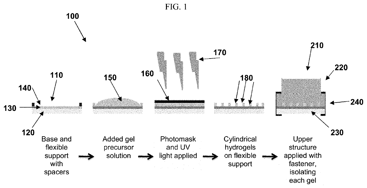
[0062]In this Example, components, photopatterning, and assembly of an exemplary system is described.

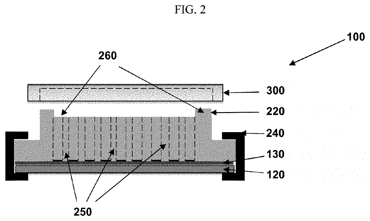
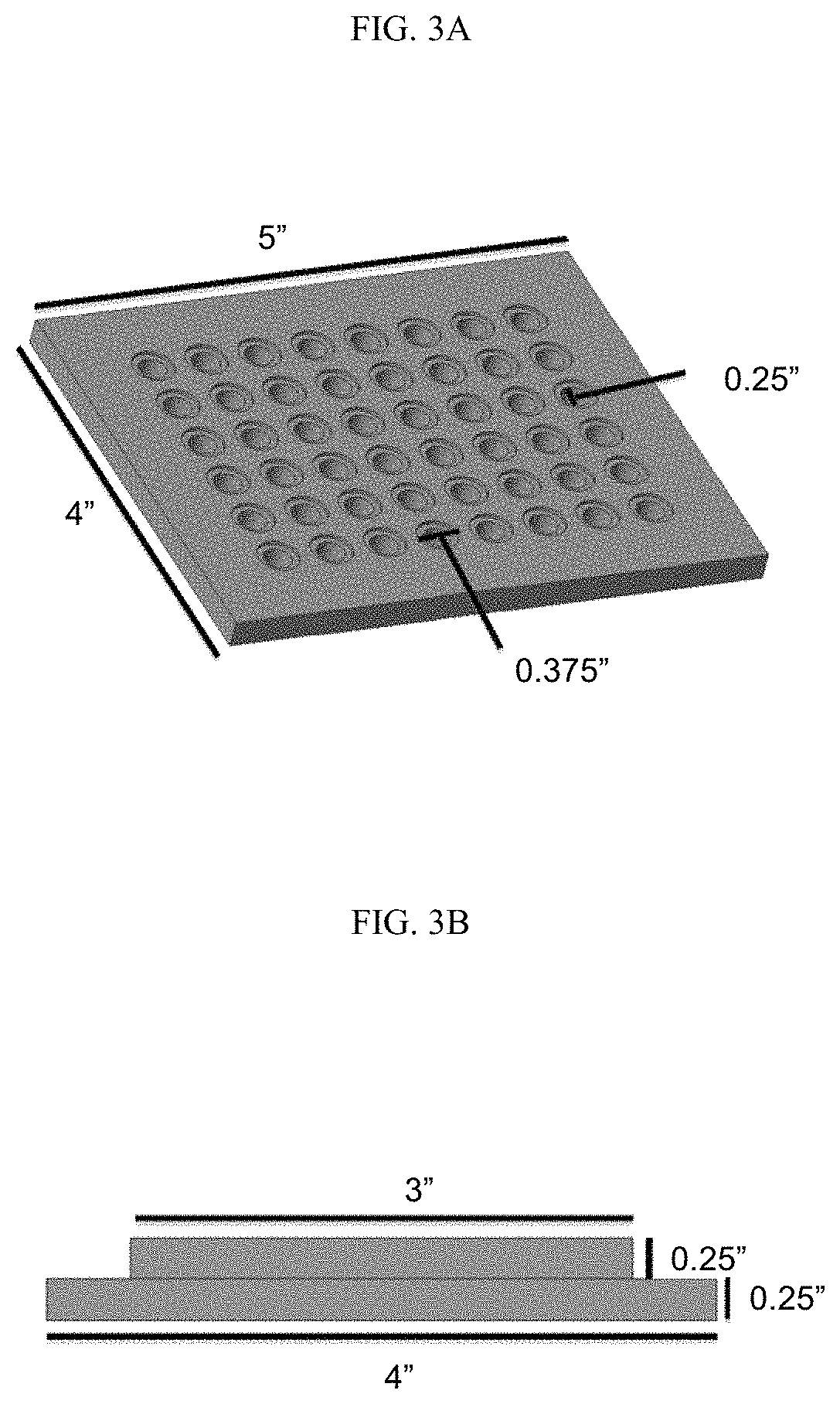
[0063]A glass base in a rectangular shape with dimensions of 4″×5″×0.25″ was purchased (Gate City Glass & Co Inc., Kansas City, Mo.). The width and length were designed to be similar to the base of a standard multiwell plate and the height was chosen such that buckling of the base was negligible. The glass base was lined with a GelBond flexible plastic support (GELBOND®, commercially available from Lonza). The GELBOND® flexible plastic support was positioned onto the glass base hydrophobic side-down.

[0064]An upper structure was prepared from high-density polyethylene (HDPE). The dimensions of the exemplary upper structure are depicted in FIG. 3. The bottom length and width were constructed to match that of the glass base, namely 4″×5″. The upper structure included an additional 0.5″ on each side having a thickness of 0.25″ to accommodate the clamps for assembly of the device. The mid...

example 2

[0072]For rheology testing, the gels were prepared in the form of slabs of 20 mm diameter and 0.5 mm thickness and swollen in PBS for 24 h prior to measurements. The gel stiffness was measured by rheology (AR 2000ex rheometer, TA Instruments, New Castle, Del.) with a 20 mm upper parallel geometry, oscillatory frequency sweep test 1-10 Hz, and 2% constant strain. Young's modulus was related to the storage modulus by the following equation:

E=G′2(1+v)  (1)

where E is Young's modulus and v is the Poisson's ratio which was approximated to 0.5 for polyacrylamide gels.

[0073]The device was tested in the absence of hydrogels for leakage and evaporation. To test for leakage, the device was assembled and 200 μL of colored tap water was put into each well. The device was then covered with its lid and placed at 4° C. for 48 hours. Visual observation was used at assess leakage.

[0074]To test for evaporation, the device was again assembled without hydrogels. 150 μl of 10 mM PBS were placed in three ...

example 3

[0080]In this Example, cell growth, proliferation, and maintenance on the device was investigated.

[0081]Specifically, to assess the ability of the device to support cell growth and proliferation, the device was assembled with PA gels of 93.8±1.8 kPa in Young's modulus. A standard 96-well plate with PA gels of the same stiffness was used as a control. The gels in the standard 96-well plate were assembled on top of GELBOND® as described.

[0082]To compare cell viability in the device to the standard 96-well plate, 104 cells / well were seeded in three random wells in the center of both plates and cultured for 72 hours. Cell metabolic activity was tested at 24 hours, 48 hours, and 72 hours with a resazurin assay. Briefly, a working solution of 50 μM resazurin sodium salt (ACROS Organics, Morris Plains, N.J.) was prepared in 10 mM PBS (pH 7.4). This was then dispensed at volumetric ratio of 1:10 resazurin:media into each well of the custom device or the standard 96-well plate where cells we...


PUM

PropertyMeasurementUnit
Young's modulusaaaaaaaaaa

Abstract

The present invention provides a system for conservation and efficient use of energy through controlling and monitoring of devices. At least one processing controller connected to a sensor and a device, the processing controller configured to receive the ambient data from the sensor and operating parameters from the device; a user module configured to IO receive input parameters from a plurality of users; a central processing module, connected to the structure, the user module, and the admin module through wired and / or wireless connection, the central processing module configured to process the data received from the processing controller adapted in the zone of the structure and generate the optimum parameters for operating the device adapted in the zone to the structure.

Description

CROSS REFERENCE TO RELATED APPLICATIONS[0001]This application is a national phase application of PCT / US2016 / 050191, filed on Sep. 2, 2016, which claims priority to U.S. Provisional Application No. 62 / 214,593, filed on Sep. 4, 2015, each of which is hereby incorporated by reference in its entirety.STATEMENT IN SUPPORT FOR FILING A SEQUENCE LISTING[0002]A paper copy of the Sequence Listing and a computer readable form of the Sequence Listing containing the file named “SLU 15-012US_ST25.txt”, which is 698 bytes in size (as measured in MICROSOFT WINDOWS® EXPLORER), are provided herein and are herein incorporated by reference. This Sequence Listing consists of SEQ ID NOs:1-2.BACKGROUND OF THE DISCLOSURE[0003]The present disclosure relates generally to biomaterial platforms. More particularly, the present disclosure is directed to a system and methods for preparing photo-patterned hydrogel-containing multiwell plate designs. The system and methods of the present disclosure provides a fast...

Claims


Application Information

Patent Timeline
Patent Type & Authority Patents(United States)
IPC IPC(8): G03F7/20G03F7/26G03F7/027G03F1/22C12M1/32C12M1/12G03F7/038B01J19/00C12M1/00B01L3/00
CPCB01J19/0046G03F7/027G03F7/2004G03F7/2012G03F7/2014G03F1/22G03F7/038C12M23/12C12M25/14C12M23/20G03F7/2045G03F7/26B01J2219/00432B01L3/5085B01J2219/00644B01J2219/00317C12N2539/00C12N2531/00B01J2219/00711C12N2535/10B01J2219/0072B01J2219/00743
Inventor ZUSTIAK, SILVIYA PETROVAAHMED, NAVEED ZAFAR
Owner SAINT LOUIS UNIVERSITY
Learn More