Image forming apparatus
a technology of forming apparatus and forming container, which is applied in the direction of electrographic process apparatus, instruments, optics, etc., to achieve the effect of reducing the load between the mounted accommodating container and the main assembly of the apparatus
- Summary
- Abstract
- Description
- Claims
- Application Information
AI Technical Summary
Benefits of technology
Problems solved by technology
Method used
Image
Examples
embodiment 1
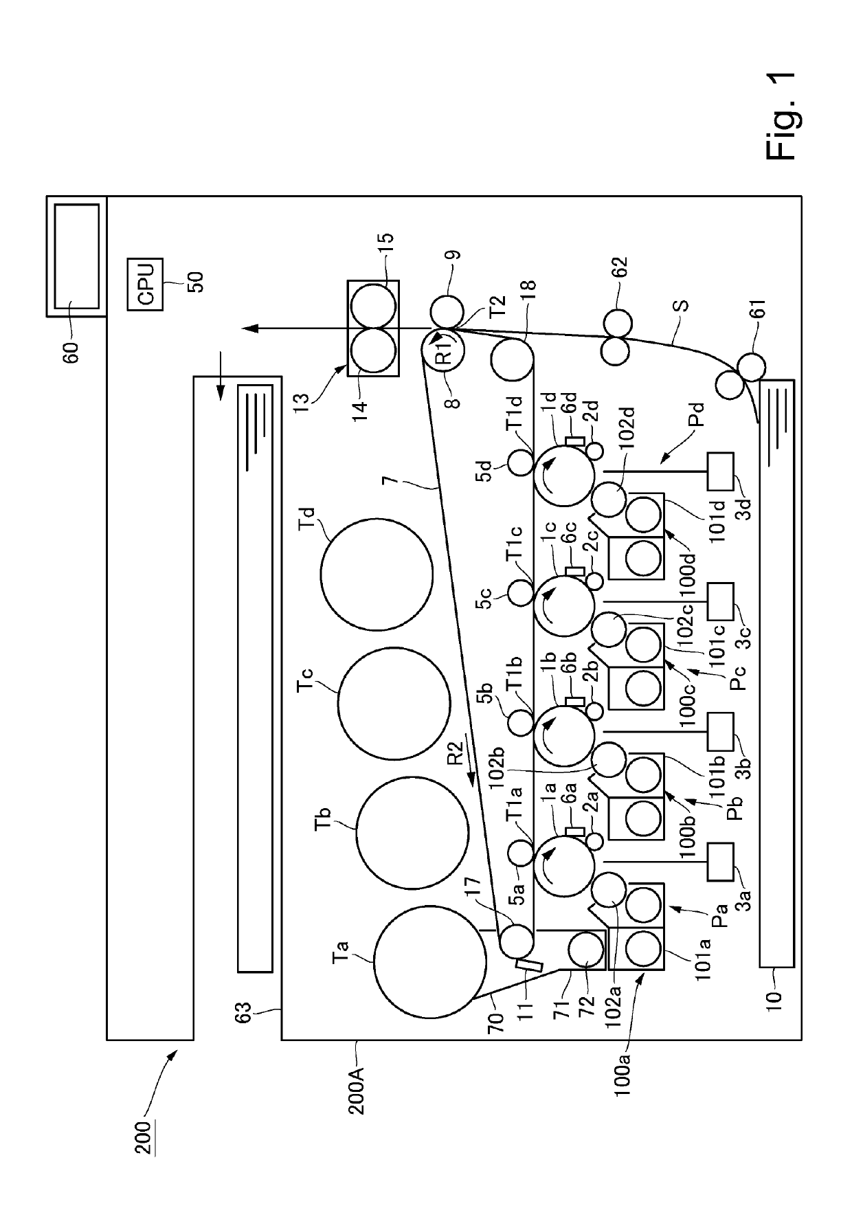
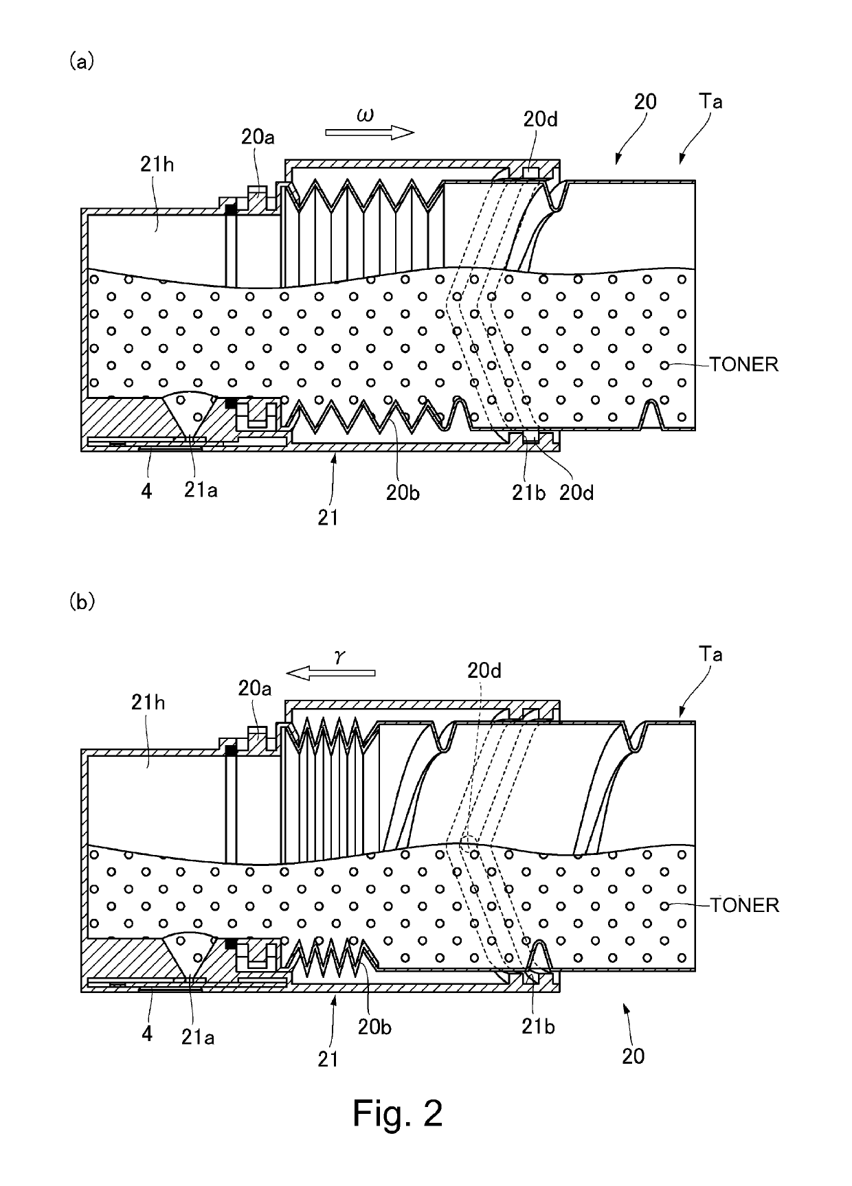
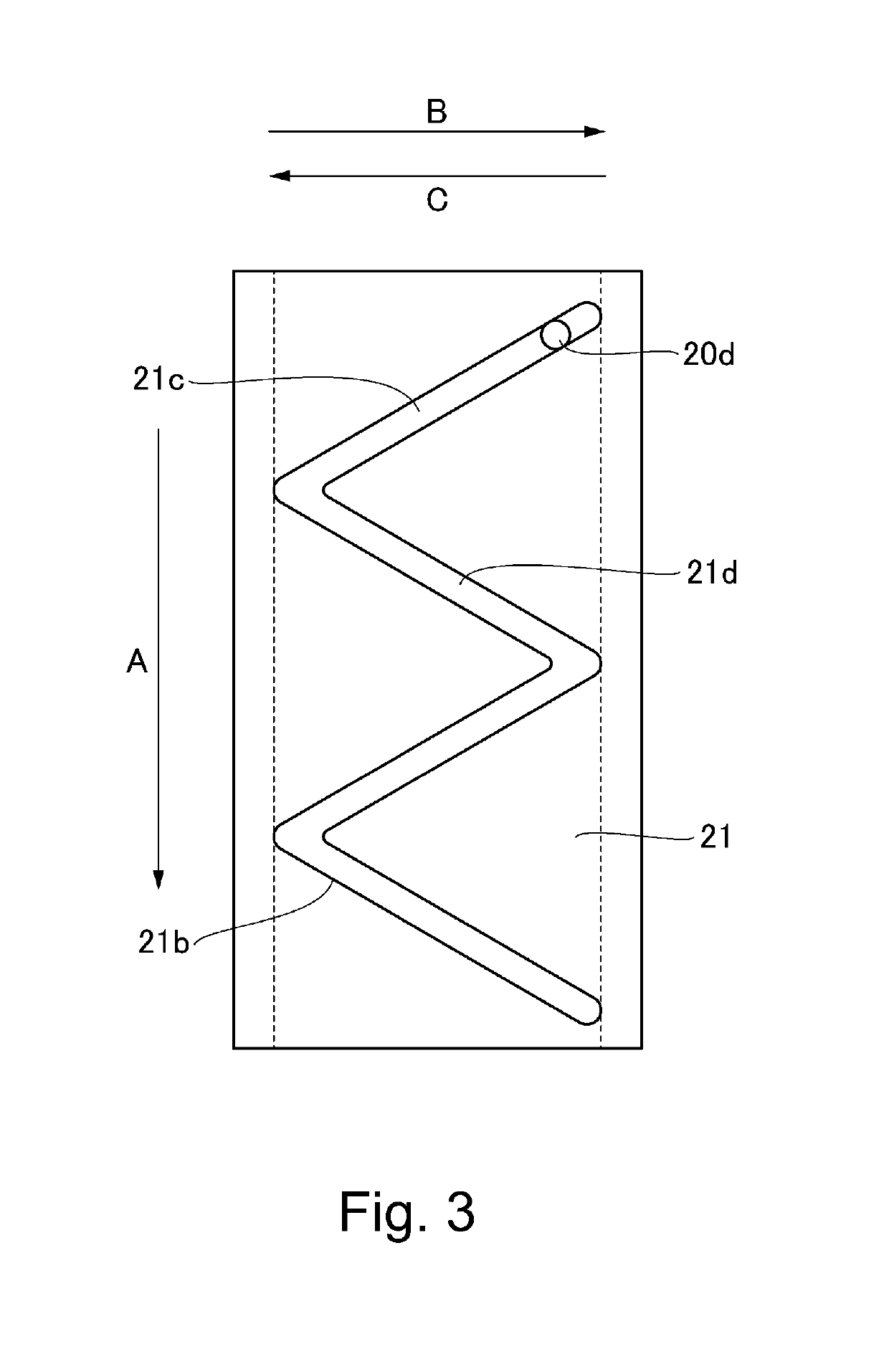
[0039]Referring to FIGS. 1 to 16, an Embodiment 1 will be described. First, a schematic structure of the image forming apparatus of this embodiment will be described referring to FIG. 1.
[Image Forming Apparatus]
[0040]The image forming apparatus 200 is a color image forming apparatus using an electrophotographic process, and is an image forming apparatus of a so-called intermediary transfer tandem type in which four color image forming stations Pa to Pd are provided above the intermediary transfer belt 7 side by side. In this embodiment, the image forming apparatus 200 forms an image with four colors of yellow (Y), magenta (M), cyan (C), and black (Bk). The number of colors is not limited to four, and the order of colors is not limited to this.
[0041]The image forming apparatus 200 forms a toner image (image) on the recording material S, in accordance with an image signal from an original reading device (not shown) connected to the apparatus main assembly 200A or a host device such as...
second embodiment
[0105]Second Embodiment will be described using FIGS. 17 to 21. In the First Embodiment described above, the regulating member 500 was mounted to the grip 25 of the accommodating container Ta, so that the position of the accommodating container Ta was regulated to the second position. On the other hand, in this embodiment, the position of the accommodating container Ta is regulated to the second position by a container stopper 601 as a regulating means and a movable member. Other constitutions and functions are similar to those in the above-described First Embodiment, and therefore, similar constituent elements are represented by the same reference numerals or symbols and description and illustration thereof will be omitted or simplified. In the following, a portion different from the First Embodiment will be principally described.
[0106]As shown in with reference to FIGS. 17 and 18, on the rear-side plate 202, a toner supplying portion 400A on the apparatus main assembly side where ...
third embodiment
[0123]Third Embodiment will be described using FIGS. 22 to 25. In the Second Embodiment described above, the container stopper 601 was moved by driving the driving motor 606. On the other hand, in this embodiment, drive for moving the container stopper 601 is carried out by the same driving source as drive of the accommodating container Ta. Other constitutions and functions are similar to those in the above-described Second Embodiment, and therefore, similar constituent elements are represented by the same reference numerals or symbols and description and illustration thereof will be omitted or simplified. In the following, a portion different from the Second Embodiment will be principally described.
[0124]As shown in with reference to FIG. 22, on the rear-side plate 202, a toner supplying portion 400B on the apparatus main assembly side where a supplying toner (toner for supply) is supplied from the accommodating container Ta to the developing device 100a is provided. Incidentally, ...
PUM
 Abstract
Description
Claims
Application Information
 - R&D
- Intellectual Property
- Life Sciences
- Materials
- Tech Scout
- Unparalleled Data Quality
- Higher Quality Content
- 60% Fewer Hallucinations
Browse by: Latest US Patents, China's latest patents, Technical Efficacy Thesaurus, Application Domain, Technology Topic, Popular Technical Reports.
© 2025 PatSnap. All rights reserved.Legal|Privacy policy|Modern Slavery Act Transparency Statement|Sitemap|About US| Contact US: help@patsnap.com


