Method and apparatus for grinding axial workpieces

a technology of workpieces and axial shafts, which is applied in the direction of grinding machine components, other manufacturing equipment/tools, manufacturing tools, etc., can solve the problems of affecting the work environment, affecting increasing the cost of fluid treatment, so as to reduce the load between the workpiece and the elastic grinding stone, reduce the rotational speed of the grinding stone, and reduce the cost of facilities and electricity charges

Active Publication Date: 2013-10-29
NTN CORP
View PDF18 Cites 0 Cited by
  • Summary
  • Abstract
  • Description
  • Claims
  • Application Information

AI Technical Summary

Benefits of technology

[0011]Since the present invention employs an elastic grinding stone, elastic bodies carrying abrasive grains operate resiliently, thereby allowing projected abrasive grains to be resiliently displaced flush with the face and thus the projections and depressions of the grinding stone to be averaged. Since this causes the load between the workpiece and the elastic grinding stone to be reduced, it is possible to prevent the abrasive grains from causing chipping, thereby providing grinding without the chipping that may lead to concentration of stress due to heat or degradation in bending strength. Since a reduced load can also serve to reduce the rotational speed of the grinding stone, heat to be generated on the workpiece and grinding stone is reduced, thereby eliminating the need for using cooling water. It is thus made possible to provide dry grinding (grinding without using liquid such as water) which is suitable for grinding a workpiece having an already processed portion to which dust particles or water are not desired to adhere.
[0012]According to the present invention, use of the elastic grinding stone makes it possible to remove a turning lead portion by dry grinding without causing grinding burning. Additionally, the grinding causes only an extremely reduced amount of dust particles without the need of providing facilities for grinding fluid, thereby cutting the costs of the facilities and electricity charges therefor, which would be otherwise required. It is also possible to solve those problems such as deterioration of work environment due to scattering of grinding fluid or with the treatment of used fluids.
[0013]Additionally, the grinding apparatus can be readily incorporated into a typical lathe. This allows for freely selecting within the lathe either only processing for finish cutting of quenched steel or processing for finish cutting of quenched steel followed by removal of a turning lead portion with the elastic grinding stone. This selection may vary. For example, even for those axial workpieces that are used with constant velocity joints of the same type, it may depend on the type number thereof whether or not their turning lead portions have to be removed. However, regardless of such cases, it is possible to process those axial workpieces in the same line, thereby providing reductions in manufacturing costs through shared use of a line.

Problems solved by technology

Such a remaining coarse turning lead portion may likely cause leakage of oil along the turning lead portion.
Use of grinding fluid causes deterioration of work environment due to scattering of the fluid or an increase in costs for treatment of used fluids.
However, in an outer-diameter finish step for axial parts having an oil seal fit portion on their outer circumferential surface, it is difficult to generally employ dry processing by entirely changing grinding to cutting because there will still be a possibility that a coarse turning lead portion inevitably remains.

Method used


Image

  • Method and apparatus for grinding axial workpieces
  • Method and apparatus for grinding axial workpieces
  • Method and apparatus for grinding axial workpieces

Examples


Embodiment Construction

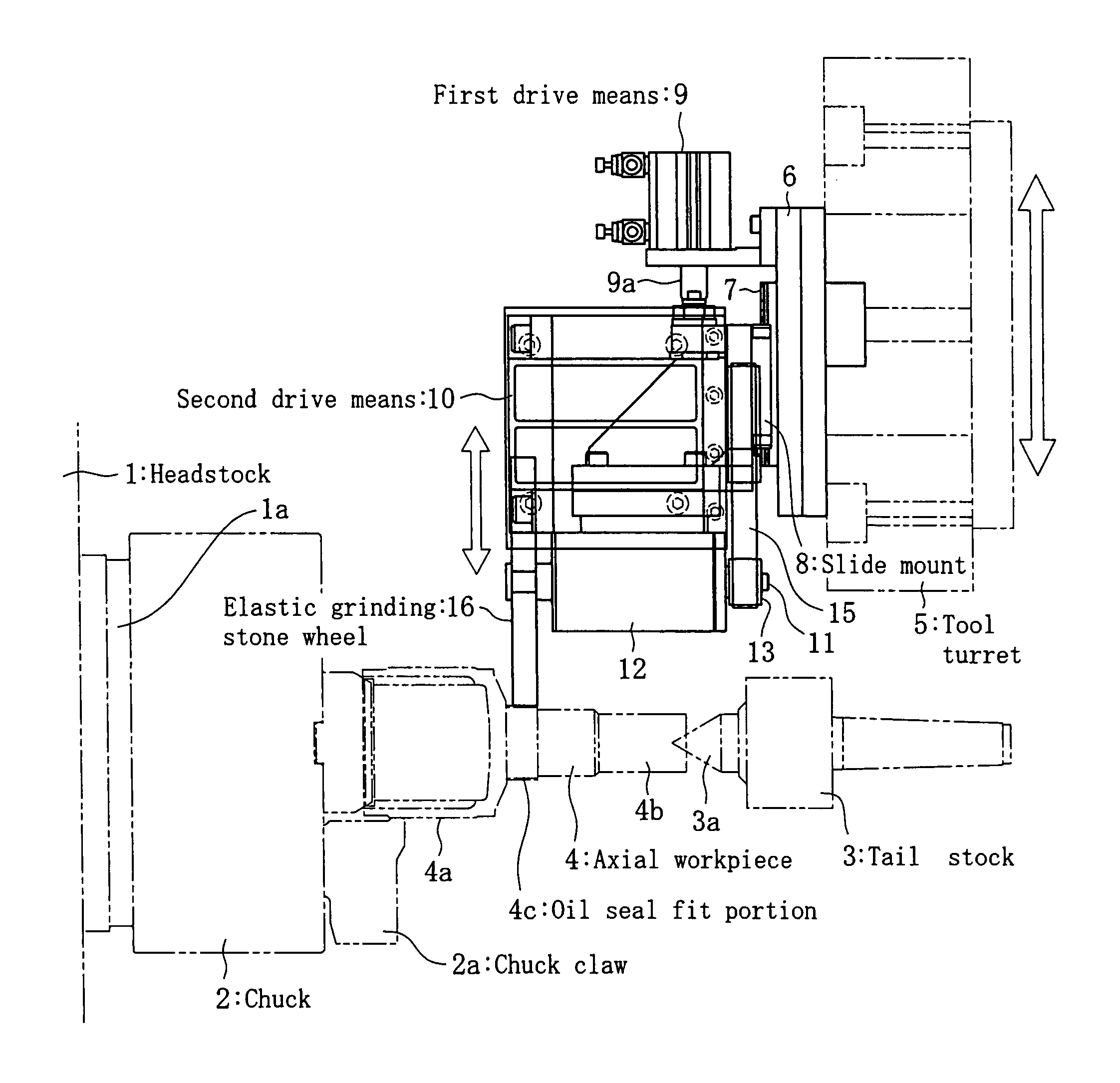
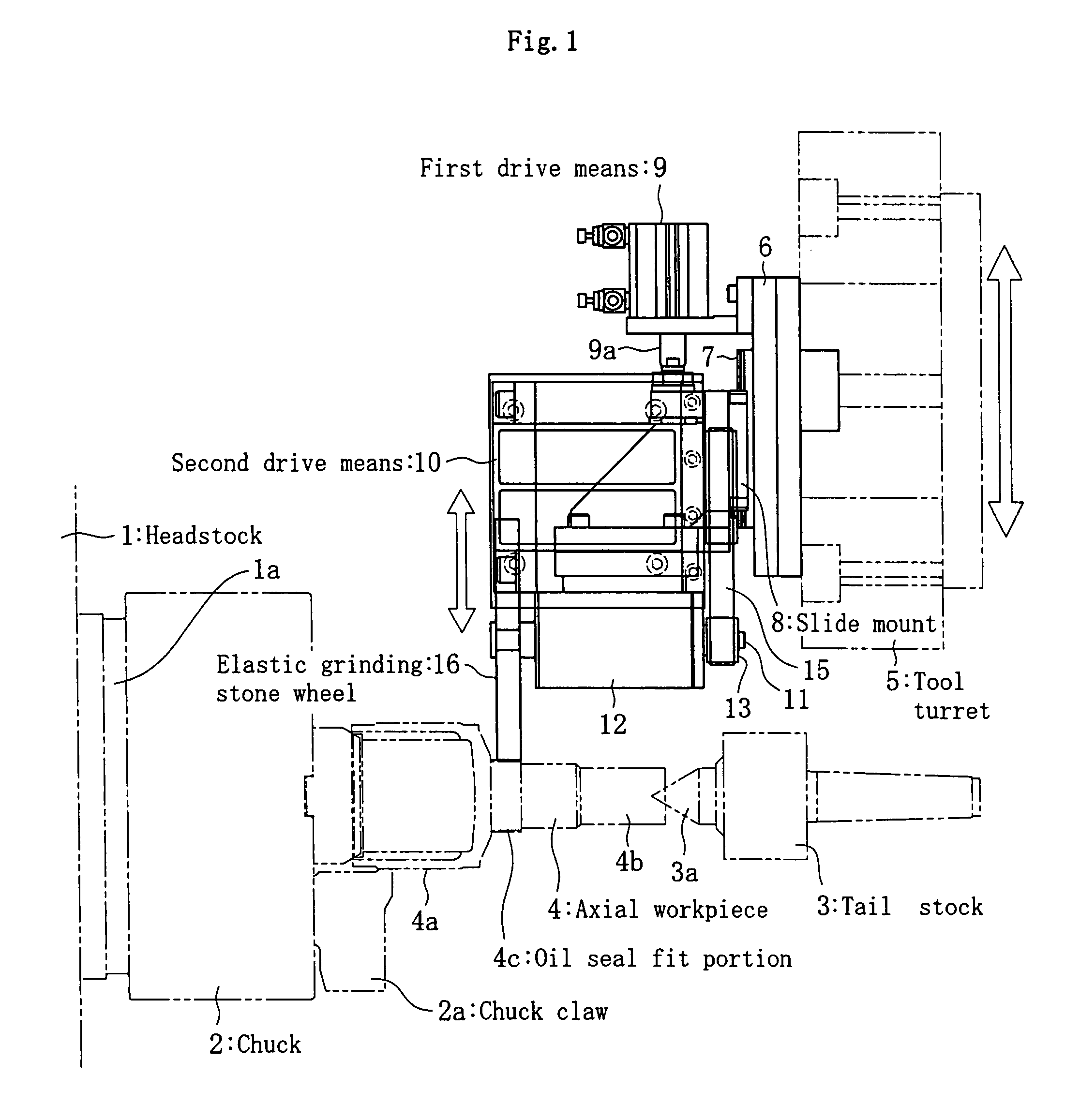
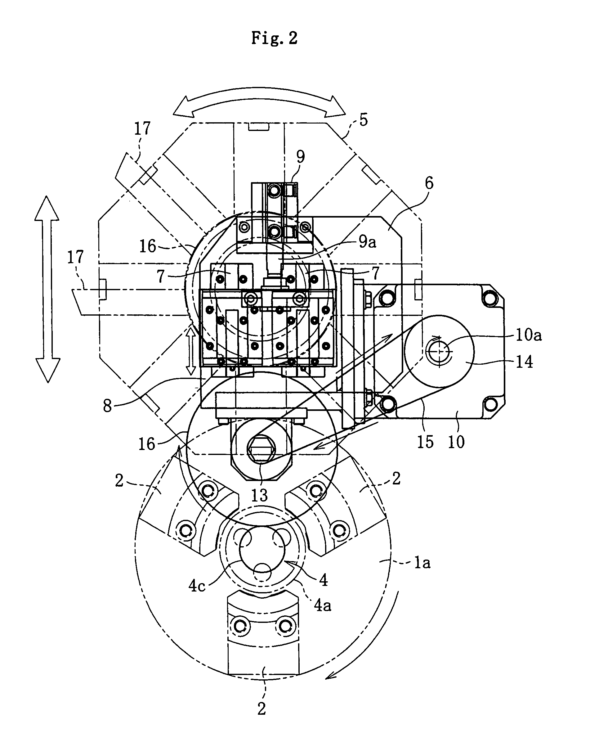
[0017]The present invention will now be described below with reference to the accompanying drawings in accordance with the embodiment. In FIGS. 1 and 2, there are shown a headstock 1 of a lathe, a three-claw chuck 2 attached to a main shaft 1a of the headstock 1, and a tail stock 3 opposing to the headstock 1. Note that other components such as a bed on which the tail stock 3 is installed are not illustrated in these drawings.

[0018]In this embodiment, illustrated as an exemplary axial workpiece having an oil seal fit portion on its outer circumferential surface is an outer joint member 4 of a sliding-type constant velocity universal joint. One end of the outer joint member 4 has a shape of a shaft attached cup in which a tip portion of the chuck 2 is fit into the inner diameter of a cup portion 4a and the outer diameter of the cup portion 4a is securely held with a chuck claw 2a. On the other hand, a center 3a of the tail stock 3 abuts against the center of the tip portion of a shaf...


PUM

PropertyMeasurementUnit
constant pressureaaaaaaaaaa
outer-diameteraaaaaaaaaa
elasticaaaaaaaaaa

Abstract

A method and an apparatus for grinding an axial workpiece are capable of removing a turning lead portion of an axial workpiece having an oil seal fit portion on its outer circumferential surface by grinding without any grinding fluid. The apparatus includes a headstock of a lathe for rotatably supporting an axial workpiece about its axis, the workpiece having an oil seal fit portion on its outer circumferential surface, and a slide mount disposed so as to be radially movable with respect to a tool turret of the lathe. The apparatus also includes an air cylinder for moving the slide mount back and forth in alignment with the axis of the headstock, an elastic grinding stone wheel rotatably attached to the slide mount to be movable radially back and forth with respect to the oil seal fit portion by the slide mount being moved, and a brushless motor for rotating the elastic grinding stone wheel.

Description

BACKGROUND OF THE INVENTION[0001]1. Field of the Invention[0002]The present invention relates to a method and an apparatus for grinding axial workpieces, and in particular, to a method and an apparatus for grinding an axial workpiece having an oil seal fit portion on its outer circumferential surface to remove a turning lead portion thereof by dry process within a lathe.[0003]2. Description of the Related Art[0004]A number of constant velocity joints and other various types of automobile components include those axial parts that have an oil seal fit portion on their outer circumferential surface. Such axial parts are typically formed by grinding, but when formed by turning using a lathe, they may have somewhat coarse turning lead portions remaining at their oil seal fit portion. Such a remaining coarse turning lead portion may likely cause leakage of oil along the turning lead portion. Accordingly, the oil seal fit portion is generally finished by grinding to remove the turning lead...

Claims


Application Information

Patent Timeline
Patent Type & Authority Patents(United States)
IPC IPC(8): B24B49/00B24B1/00
CPCB23B3/168B24B5/04B24B5/36B23P23/02
Inventor TANIO, MASAYUKIMUTO, AKIYOSHI
Owner NTN CORP
Why Eureka
Try Eureka