
Connector

a technology of connecting rods and shields, applied in the direction of coupling contact members, coupling device connections, electrical apparatus, etc., can solve the problems of increasing the size of the connector, and achieve the effect of reducing the size of the housing, and reducing the size of the shield member

Active Publication Date: 2020-08-04
IRISO ELECTRONICS CO LTD
View PDF26 Cites 6 Cited by
  • Summary
  • Abstract
  • Description
  • Claims
  • Application Information

AI Technical Summary

Benefits of technology

The present disclosure is about a connector that can guide the connection target and prevent the housing from getting bigger in size. This is achieved by placing the outer side connection portions further out from the guide face, which requires the first housing to be extended in length. Overall, the connector is designed to be compact and efficient in guiding the connection target.

Problems solved by technology

However, if the outer side connection portions are disposed further toward the outer sides from the guide face, the first housing needs to be extended in the length direction in order to support the outer side connection portions, thereby increasing the size of the connector.

Method used


Image

  • Connector
  • Connector
  • Connector

Examples


Embodiment Construction

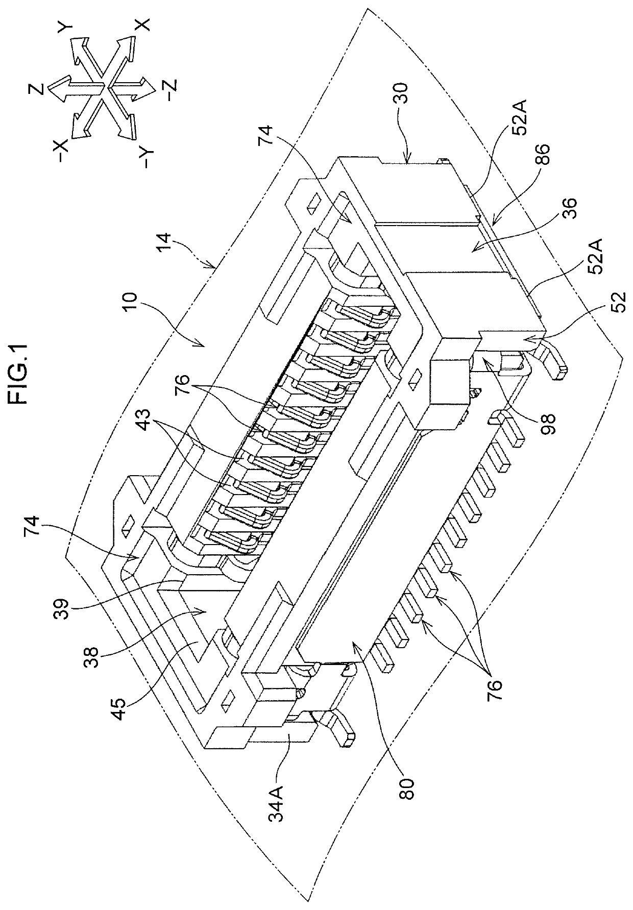
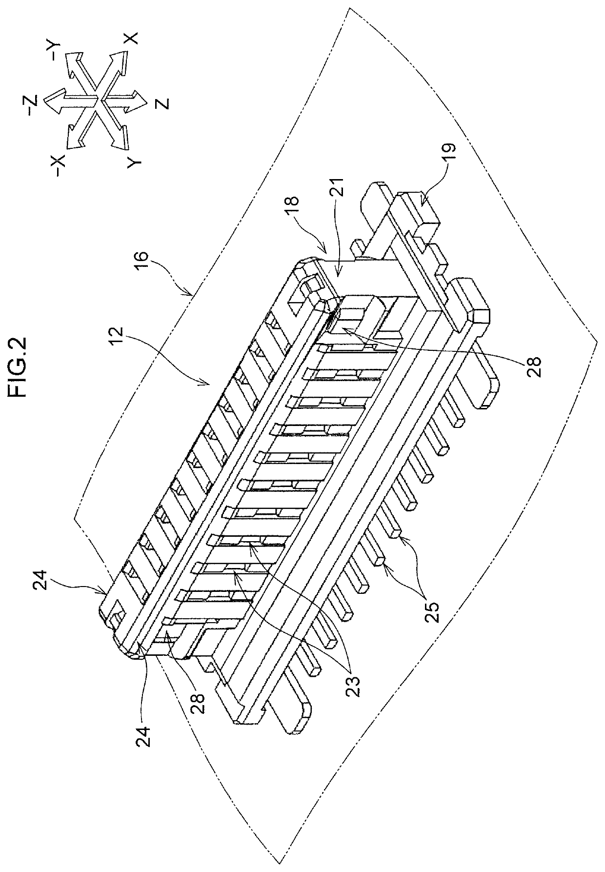
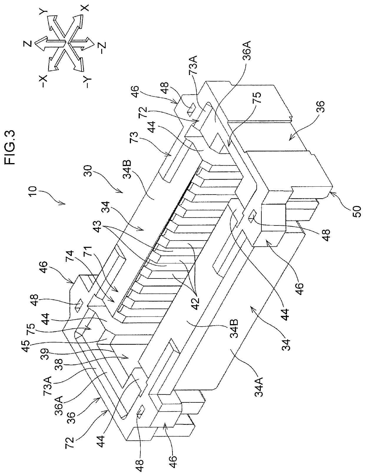
[0037]Explanation follows regarding a socket connector 10 and a plug connector 12 according to an exemplary embodiment.

[0038]Overall Configuration

[0039]The socket connector 10 illustrated in FIG. 1 is an example of a connector. The plug connector 12 (see FIG. 2), described later, can be inserted into and removed from the socket connector 10. In the below explanation, an insertion-removal direction in which the plug connector 12 is inserted into and removed from the socket connector 10 is referred to as the Z direction. In a plane (not illustrated in the drawings) orthogonal to the Z direction, a length direction of the socket connector 10 is referred to as the X direction, and a breadth direction of the socket connector 10 is referred to as the Y direction. The X direction, the Y direction, and the Z direction are mutually orthogonal to one another. The X direction corresponds to a second direction intersecting the insertion-removal direction of the connector. The Y direction corres...


PUM


Abstract

A connector includes a housing and a shield member. The housing includes an insertion-removal section and a guide face, a connection target is inserted into or removed from the insertion-removal section through an insertion-removal port in an insertion-removal direction, and the guide face is formed at a peripheral portion of the insertion-removal section so as to guide the connection target toward the insertion-removal section. The shield member includes a pair of shield portions and a coupling portion. The pair of shield portions are disposed on both sides of the housing in a first direction intersecting the insertion-removal direction, the coupling portion couples the pair of shield portions together in the first direction, the coupling portion contacts a location of the housing on an opposite side to the insertion-removal port in the insertion-removal direction, and the coupling portion at least partially overlaps the guide face as viewed in the insertion-removal direction.

Description

CROSS-REFERENCE TO RELATED APPLICATION[0001]This application claims priority under 35 USC 119 from Japanese Patent Application No. 2018-079201 filed Apr. 17, 2018, the disclosure of which is incorporated by reference herein in its entirety.BACKGROUNDTechnical Field[0002]The present disclosure relates to a connector.Related Art[0003]In Japanese Patent Application Laid-Open (JP-A) No. 2016-9619, a first connector includes a first housing that fits together with a second connector, plural first terminals that form an electrical connection with second terminals of the second connector, a pair of first reinforcing metal fittings, and a pair of shield plate portions. The pair of first reinforcing metal fittings include outer side connection portions that cover a pair of end faces of the first housing.SUMMARY[0004]In the connector of JP-A No. 2016-9619, length direction end portions of the first housing are covered from a side closer to the second connector by outer side connection portion...

Claims


Application Information

Patent Timeline
Patent Type & Authority Patents(United States)
IPC IPC(8): H01R12/71H01R12/73H01R12/70H01R13/6587H01R13/6582H01R13/405
CPCH01R12/73H01R12/7005H01R13/6582H01R13/405H01R12/716H01R13/6587H01R13/6581H01R13/629H01R13/20H01R13/6594H01R12/712
Inventor YUKUTAKE, HIROAKIOHKUMA, YOSHIHITOSUZUKI, HITOSHI
Owner IRISO ELECTRONICS CO LTD
Learn More