Methods and systems for a conveyor assembly

a conveyor and assembly technology, applied in conveyors, conveyors, jigging conveyors, etc., can solve the problems of time-consuming and physical demands, difficult cleaning or replacement by operators, etc., and achieve the effect of cleaning and service more quickly, consistent and uniform locomotion of conveyor pans

Active Publication Date: 2020-08-11
PPM TECH HLDG LLC
View PDF7 Cites 0 Cited by
  • Summary
  • Abstract
  • Description
  • Claims
  • Application Information

AI Technical Summary

Benefits of technology

[0006]However, the inventors herein have recognized potential solutions to production delays as a result of cleaning or servicing the conveyor assembly. In one example, the issues described above may be addressed by a conveyor system comprising a drive carriage comprising a plurality of magnets spaced away from a drive motor, and where the magnets apply a force to a conveyor pan in a direction perpendicular to a direction of movement of the conveyor pan. In this way, the conveyor pan is removable from the conveyor assembly without loosening bolts or the like.
[0007]As one example, the conveyor assembly may be cleaned and serviced more quickly. Additionally, the plurality of magnets may provide a more consistent and uniform locomotion of the conveyor pan. Bolts and other fasteners may degrade over time due to frictional forces, however, the magnetic field supplied by the magnets may not degrade over time, thereby providing a uniform relation between the conveyor pan and the drive motor. Additionally, decoupling of the conveyor pan from the drive carriage may be faster than loosening one or more bolts. The decoupling may occur in response to actuating a lever. As such, the magnetic force may only be overcome in response to an external force (e.g., a user actuating a lever) and not due to the conveyance of items on the conveyor pan.

Problems solved by technology

Conveyor assemblies may comprise relatively large components, such as a conveyor pan, that may be difficult for operators to clean or replace due to the complex connection of the conveyor pan to a drive motor and / or a conveyor mount.
As one example, due to the difficulty of the conveyor pan of a conveyor, one or more tools and people may be needed to loosen and remove the conveyor pan to access components arranged below the conveyor pan, such as the drive motor and / or the conveyor mount.
Therefore, if the conveyor assembly demands servicing (e.g., cleaning, repair, and / or the like), then bolts and other fasteners are loosened prior to a conveyor pan being removed, which may be time consuming and physically demanding.

Method used


Image

  • Methods and systems for a conveyor assembly
  • Methods and systems for a conveyor assembly
  • Methods and systems for a conveyor assembly

Examples


embodiment 300

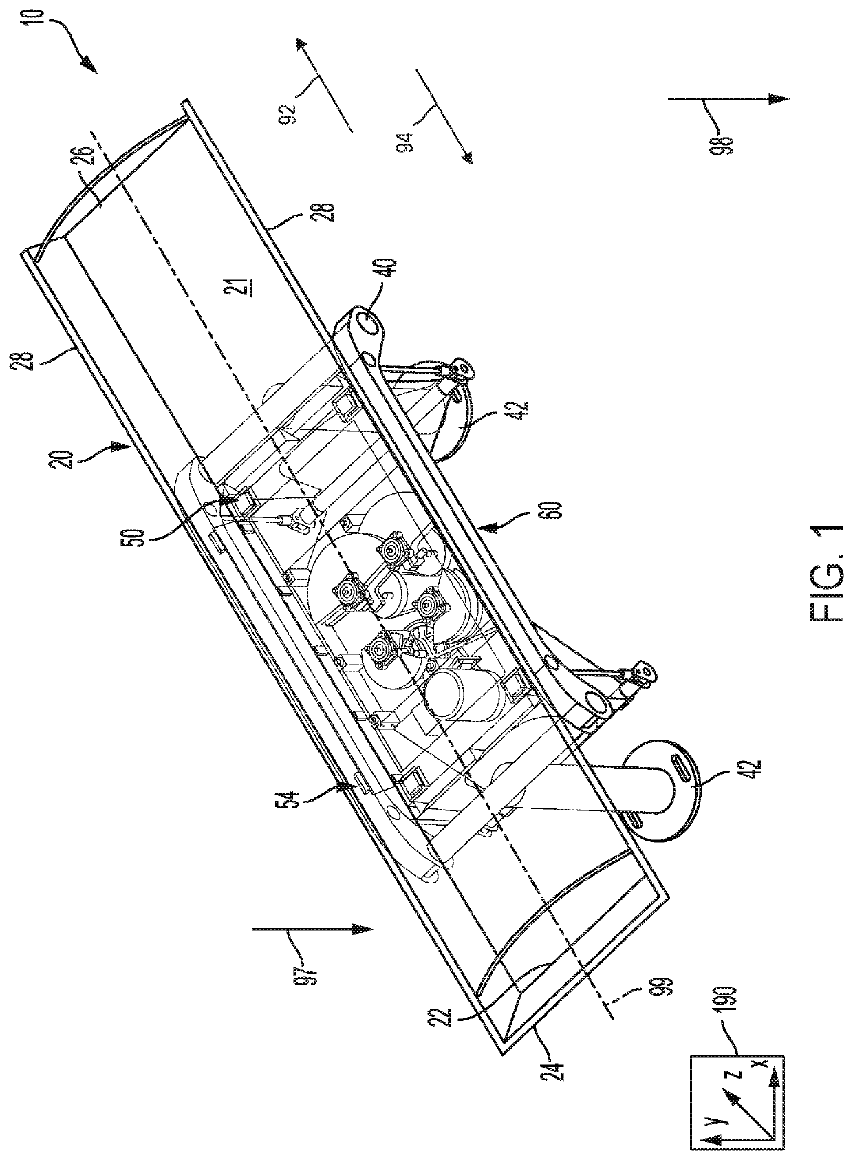
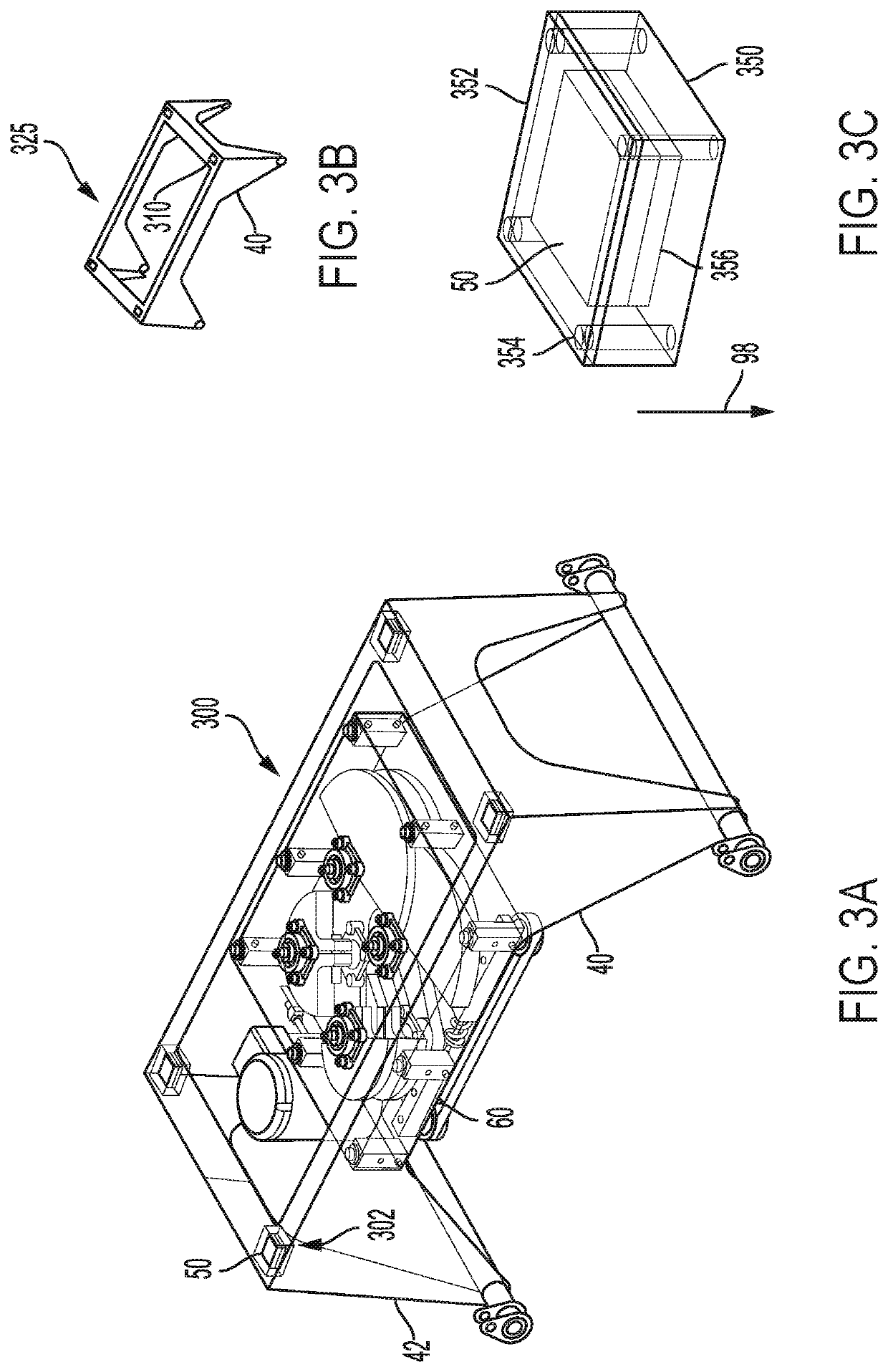
[0057]Turning now to FIG. 3A, it shows a detailed view of an embodiment 300 of the drive carriage 40 and the drive motor 60. As described above, the drive motor 60 may be mounted to the drive carriage 40 via a plurality of fasteners. The fasteners may only couple the drive motor 60 to the drive carriage 40 and do not interact with a conveyor pan (e.g., conveyor pan 20 of FIG. 1). The drive motor 60 may be physically coupled to a portion of the drive carriage 40 between each of the legs 42. The drive motor 60 may be spaced away from the conveyor pan when the conveyor pan is fully locked with the drive carriage 40 (as shown in FIGS. 1 and 2B) so that the drive motor 60 does not touch the conveyor pan.

embodiment 325

[0058]FIG. 3B shows an embodiment 325 of the drive carriage 40 with the magnets 50 removed. Cutouts 310 of the drive carriage are illustrated, wherein the cutouts 310 expose the magnets 50 arranged therebelow, as shown in FIG. 3A. The cutouts 310 may be shaped similarly to a shape of the magnets 50. Additionally or alternatively, a size of the cutouts 310 may be equal to or less than a size of the magnets 50. In one example, the cutouts 310 are smaller than the magnets 50. In one embodiment, the cutouts 310 and the magnets 50 are square. In some examples, the cutouts 310 may comprise a length less than 5 inches and the magnets 50 may comprise a length less than 7 inches. In some examples, additionally or alternatively, the cutouts 310 may comprise length less than 4 inches and the magnets 50 may comprise a length less than 6 inches. In some examples, additionally or alternatively, the cutouts 310 may comprise length less than 3 inches and the magnets 50 may comprise a length less th...


PUM


Abstract

Methods and systems are provided for a conveyor system. In one example, a system may include a drive carriage comprising a plurality of magnets configured to magnetically couple to a conveyor pan. The plurality of magnets may be configured to maintain the conveyor pan in a fully locked position as the drive carriage actuates the conveyor pan.

Description

CROSS REFERENCE TO RELATED APPLICATIONS[0001]The present application claims priority to U.S. Provisional Application No. 62 / 627,136, entitled “METHODS AND SYSTEMS FOR A CONVEYOR ASSEMBLY”, and filed on Feb. 6, 2018. The entire contents of the above-listed application are hereby incorporated by reference for all purposes.FIELD[0002]The present description relates generally to conveyors having magnetically coupled components.BACKGROUND AND SUMMARY[0003]Conveyors may be used in a wide variety of industries for transportation of bulk materials or small parts. Additionally, some conveyors may be used to perform processing operations such as screening, transferring, heating, cooling, and other such processing operations on bulk materials such as food products, sand, gravel, foundry parts, or the like.[0004]The inventors have identified some shortcomings in some conveyor assemblies, particularly in conveyor assemblies which fasten one or more components together. Conveyor assemblies may co...

Claims


Application Information

Patent Timeline
Patent Type & Authority Patents(United States)
IPC IPC(8): B65G23/18
CPCB65G23/18B65G27/08B65G21/06
Inventor REESER, DEVIN RAYDOERN, ERIC JASON
Owner PPM TECH HLDG LLC
Why Eureka
Try Eureka