Lubricating-oil collection cap for turbomachine equipment

a technology of oil collection cap and turbomachine equipment, which is applied in the direction of machines/engines, gearing details, liquid fuel engines, etc., can solve the problems of poorly controlled radial components of jets, disappearing,

Active Publication Date: 2020-08-11
SN DETUDE & DE CONSTR DE MOTEURS DAVIATION S N E C M A
View PDF22 Cites 0 Cited by
  • Summary
  • Abstract
  • Description
  • Claims
  • Application Information

AI Technical Summary

Benefits of technology

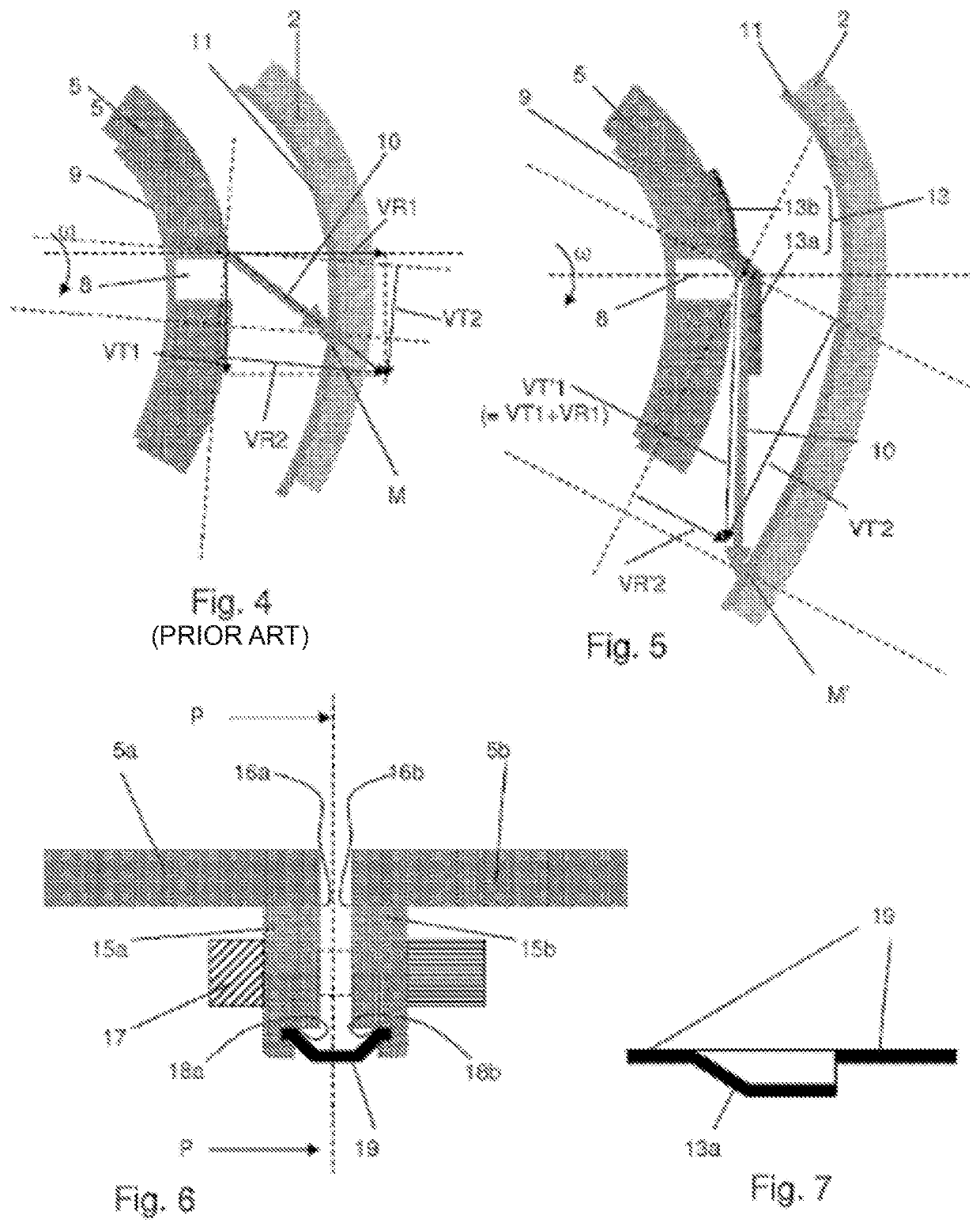
[0009]The outlet of said through orifices emerges on the radially outer wall of the cap. By deflecting the oil jet tangentially at the outlet of the orifices of the rotating cap, the radial component of the jet, which is poorly controlled, disappears. Furthermore, the speed of the jet is added to the peripheral speed at the outlet of the through orifice. The oil jets leaving the cap therefore have a better controlled orientation. Furthermore, the tangential impulse of the oil sprayed on the inner wall of the enclosure is stronger. The conditions are therefore met to improve the overall rotation of this oil against the wall of the enclosure and limit splashes.
[0017]This makes it possible to ensure proper guiding by spinning of the oil inside the cap to discharge it.
[0018]Advantageously, said orifices form small, substantially radial orientation lines in a wall thickness of said cap. The radial orientation is useful to collect the oil by spinning. Furthermore, maintaining this orientation of the extension of the line makes production easy by machining means. Preferably, the through orifices are arranged in a maximum thickness zone of the wall of the cap. This makes it possible to elongate the small lines and better drive the oil passing through these lines.

Problems solved by technology

By deflecting the oil jet tangentially at the outlet of the orifices of the rotating cap, the radial component of the jet, which is poorly controlled, disappears.

Method used


Image

  • Lubricating-oil collection cap for turbomachine equipment
  • Lubricating-oil collection cap for turbomachine equipment

Examples


Embodiment Construction

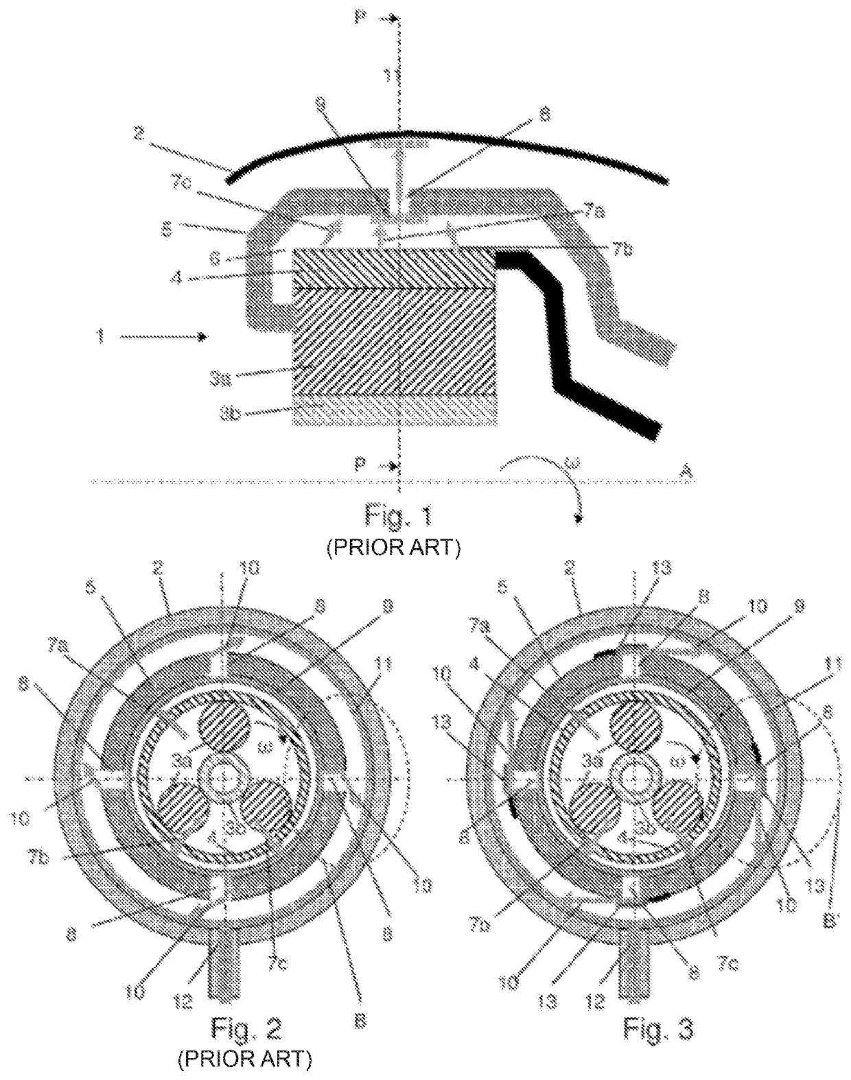
[0031]FIG. 1 shows a turbomachine equipment 1, mounted in an enclosure 2 and rotatable around an axis A. Generally, the walls of the enclosure 2 are formed by at least one annular case 2 extending around the equipment 1.

[0032]This equipment 1 is for example a reduction gear of the PGB type. An oil inlet, not shown in the figure, provides oil in the central region of the PGB to lubricate it. This oil traverses various active parts of the PGB, such as gears, by spinning. These parts are shown schematically in the figure by inner active parts 3a and 3b rotating in one direction, and surrounded by an outer part 4, rotating in the opposite direction or stationary, depending on the case.

[0033]In this example, in the case of a PGB with an epicyclic gear train, the innermost part 3b shows a planetary gear input shaft in the form of a drive pinion, which is mounted by a cannulated link on a turbine shaft rotating in a rotation direction while driving the PGB. The part 3a shows a planet carri...


PUM


Abstract

An annular cap for collecting lubricating oil for turbomachine equipment is configured to extend around the equipment and to rotate about an axis. The cap includes through-orifices through which the oil can pass radially under the effect of spinning. The cap further includes means of deflecting the oil leaving the orifices in a direction substantially transverse to the axis and substantially tangential to the cap.

Description

FIELD AND BACKGROUND OF THE INVENTION[0001]The present invention relates to the field of lubrication for aircraft engines. It more particularly relates to a device for collecting oil that has been used by a piece of equipment including a rotary part.[0002]For example, a turboprop with counter-rotating propellers may include a power gear box (PGB) whose planet gear support rotates inside a static enclosure.[0003]The planet gear support forms a cap around the rolling bearings and gears of the PGB. The oil injected continuously into the PGB lubricates and cools the rolling bearings and gears before being sprayed by centrifugation against the planet gears support. The planet gear support includes orifices through which this oil can escape toward the static enclosure, which serves as a collection enclosure to return the oil into the lubrication circuit.[0004]The PGB requires a large quantity of oil. For effective oil collection toward the oil discharge means of the enclosure and to avoid...

Claims


Application Information

Patent Timeline
Patent Type & Authority Patents(United States)
IPC IPC(8): F04D29/08F16H57/04F01D25/18F16N31/00F02C7/06
CPCF16H57/048F01D25/18F16H57/0482F16N31/00F02C7/06F05D2260/40311F16H57/0428
Inventor PIKOVSKY, CATHERINEFARVACQUE, BENOIT GUILLAUMEMORREALE, SERGE RENÉTROHEL, MATHIEU JEAN PIERRE
Owner SN DETUDE & DE CONSTR DE MOTEURS DAVIATION S N E C M A
Why Eureka
Try Eureka