Lubricating-oil collection cap for turbomachine equipment
- Summary
- Abstract
- Description
- Claims
- Application Information
AI Technical Summary
Benefits of technology
Problems solved by technology
Method used
Image

Examples
Embodiment Construction
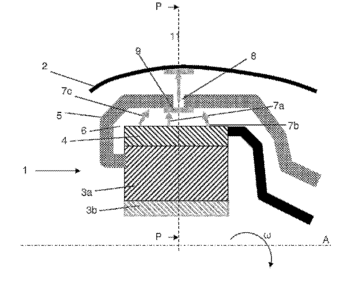
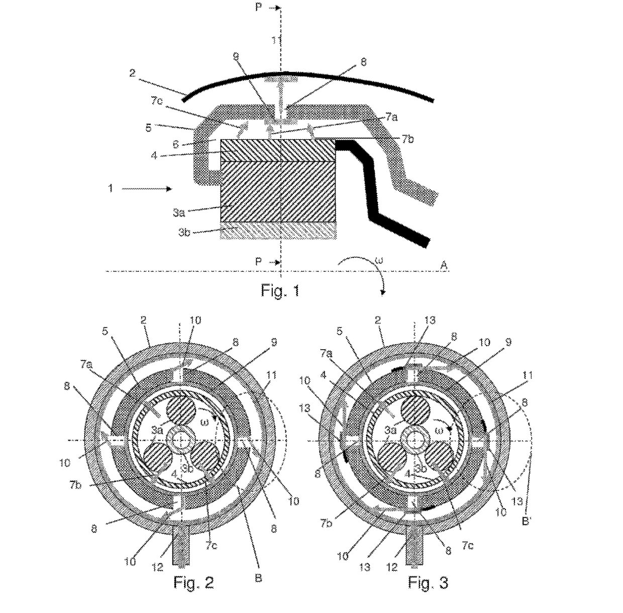
[0031]FIG. 1 shows a turbomachine equipment 1, mounted in an enclosure 2 and rotatable around an axis A. Generally, the walls of the enclosure 2 are formed by at least one annular case 2 extending around the equipment 1.
[0032]This equipment 1 is for example a reduction gear of the PGB type. An oil inlet, not shown in the figure, provides oil in the central region of the PGB to lubricate it. This oil traverses various active parts of the PGB, such as gears, by spinning. These parts are shown schematically in the figure by inner active parts 3a and 3b rotating in one direction, and surrounded by an outer part 4, rotating in the opposite direction or stationary, depending on the case.
[0033]In this example, in the case of a PGB with an epicyclic gear train, the innermost part 3b shows a planetary gear input shaft in the form of a drive pinion, which is mounted by a cannulated link on a turbine shaft rotating in a rotation direction while driving the PGB. The part 3a shows a planet carri...
PUM
 Abstract
Description
Claims
Application Information
 - R&D Engineer
- R&D Manager
- IP Professional
- Industry Leading Data Capabilities
- Powerful AI technology
- Patent DNA Extraction
Browse by: Latest US Patents, China's latest patents, Technical Efficacy Thesaurus, Application Domain, Technology Topic.
© 2024 PatSnap. All rights reserved.Legal|Privacy policy|Modern Slavery Act Transparency Statement|Sitemap