Luminaire having pliable container with restricting light exit structure and manufacturing method therof

a technology of pliable containers and light exits, applied in the field of pliable containers, can solve the problems of restricting the pliability of containers, and achieve the effect of cost-effective, straightforward and cost-effectiv

Active Publication Date: 2020-08-18
SIGNIFY HLDG BV
View PDF20 Cites 0 Cited by
  • Summary
  • Abstract
  • Description
  • Claims
  • Application Information

AI Technical Summary

Benefits of technology

[0007]The present invention further seeks to provide a more cost-effective method of manufacturing a luminaire.
[0024]This allows for the cost-effective manufacture of a luminaire that derives its structural integrity mainly from the engagement between the pliable container or covert and the light exit structure rather than from a rigid container as is the case in the prior art. This allows for the container to be shaped using straightforward and cost-effective manufacturing techniques such as for example but not limited to blistering, thermoforming, deep drawing, vacuum forming, injection molding, pressure molding and so on.

Problems solved by technology

The container is a pliable container, and the engagement between the container and the light exit structure is such that it restricts the pliability of the container.

Method used


Image

  • Luminaire having pliable container with restricting light exit structure and manufacturing method therof
  • Luminaire having pliable container with restricting light exit structure and manufacturing method therof
  • Luminaire having pliable container with restricting light exit structure and manufacturing method therof

Examples


Embodiment Construction

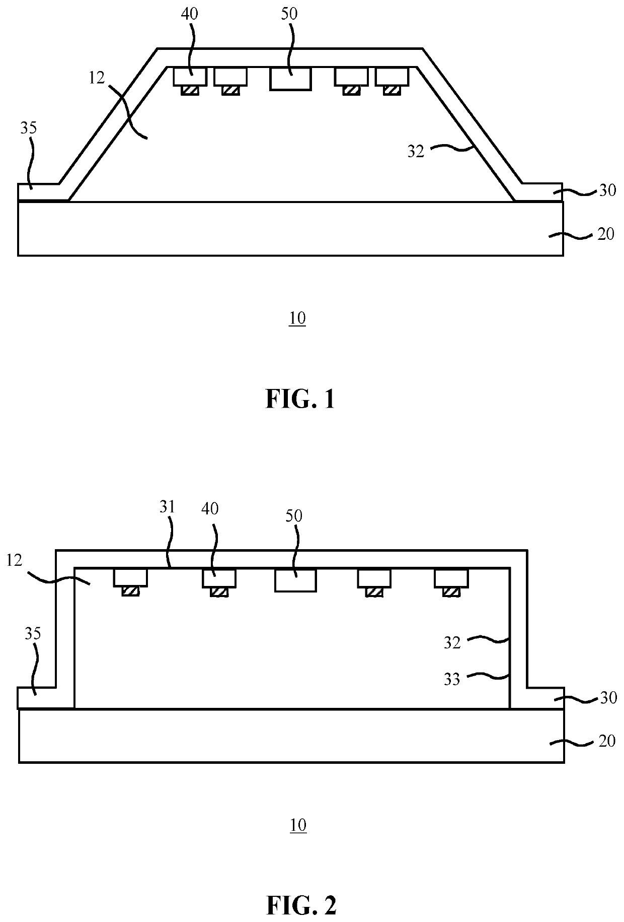
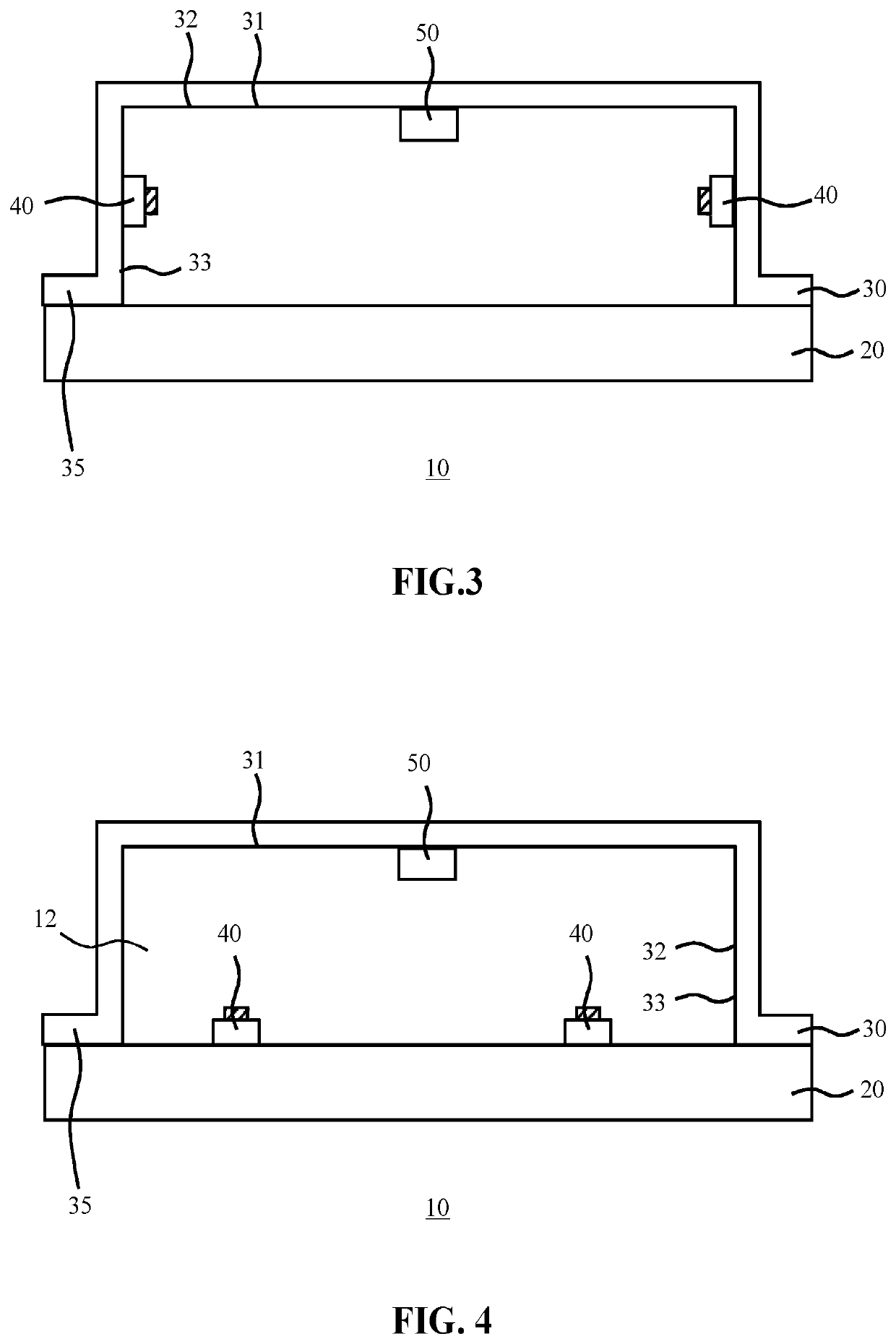
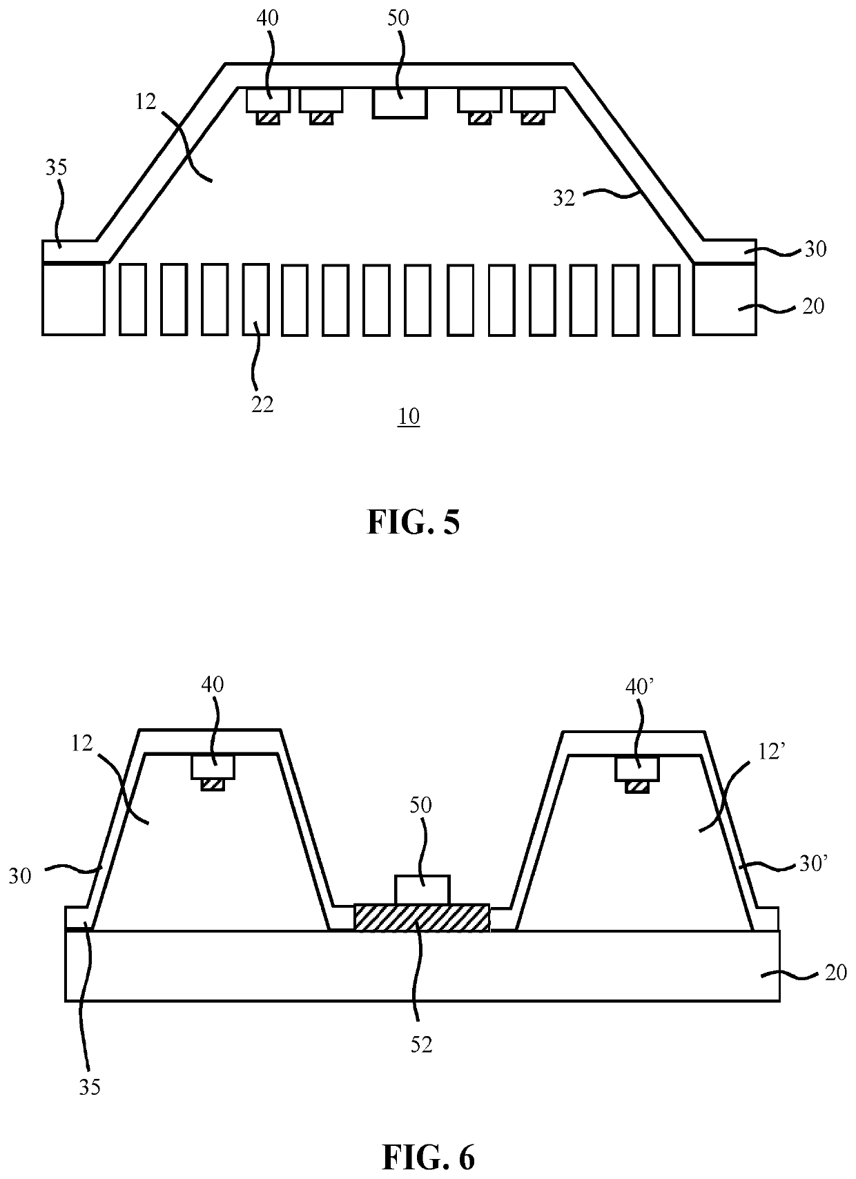
[0038]It should be understood that the Figures are merely schematic and are not drawn to scale. It should also be understood that the same reference numerals are used throughout the Figures to indicate the same or similar parts.

[0039]The present invention is based on the insight that whereas state-of-the-art of luminaires typically derive their structural integrity from a rigid cover that forms the housing of the luminaire together with the light exit structure such as a light exit window, causing the luminaire to become costly because of the manufacturing process of such a rigid cover, it is equally feasible to provide a structurally sound luminaire that derives its structural integrity from the engagement of a pliable container or cover with a light exit structure. Consequently, the luminaire container may be relatively flexible or deformable, with the luminaire cover being structurally reinforced, e.g. kept into shape or being made less flexible or deformable, by its engagement w...


PUM


Abstract

Disclosed is a luminaire (10) comprising a luminaire housing delimited by a light exit structure (20) engaging with an edge of a pliable container (30), wherein the container is structurally reinforced, i.e. rendered less pliable, by its engagement with the light exit structure; and at least one light engine (40) disposed within the luminaire housing. A method of manufacturing such a luminaire is also disclosed.

Description

CROSS-REFERENCE TO PRIOR APPLICATIONS[0001]This application is the U.S. National Phase application under 35 U.S.C. § 371 of International Application No. PCT / EP2016 / 068870, filed on Aug. 8, 2016, which claims the benefit of European Patent Application No. 15181778.0, filed on Aug. 20, 2015. These applications are hereby incorporated by reference herein.FIELD OF THE INVENTION[0002]The present invention relates to a luminaire comprising a luminaire housing having at least one light engine being disposed within, wherein the luminaire housing is delimited by a light exit structure and a container engaging with the light exit structure.[0003]The present invention further relates to a method of manufacturing such a luminaire.BACKGROUND OF THE INVENTION[0004]Luminaires are electrical devices for creating artificial light by using one or more light engines, e.g. electrical lamps such as fluorescent lamps, halogen lamps, solid state lighting (SSL) elements such as LEDs, and so on. Examples o...

Claims


Application Information

Patent Timeline
Patent Type & Authority Patents(United States)
IPC IPC(8): F21V15/01F21V23/00F21V17/16F21V29/503F21V7/04F21V17/00F21S8/02F21S8/04F21Y115/10
CPCF21S8/04F21V15/012F21S8/026F21V17/16F21V17/007F21V7/04F21V23/005F21V29/503F21Y2115/10F21S8/02
Inventor NIJKAMP, RICK GERHARDUS
Owner SIGNIFY HLDG BV
Why Eureka
Try Eureka