Back contacted solar cell

a solar cell and back contact technology, applied in the field of back contact solar cells, can solve the problems of increasing the danger of earth greenhouse effect, solar cell electricity is too expensive to be competitive with nuclear power, thermal power, solar panel electricity, etc., and achieves the effect of cost-effectiveness

Inactive Publication Date: 2010-02-11
RENEWABLE ENERGY CORP LTD
View PDF12 Cites 35 Cited by
  • Summary
  • Abstract
  • Description
  • Claims
  • Application Information

AI Technical Summary

Benefits of technology

[0006]The main objective of the invention is to provide a cost-effective manufacturing method of high-efficient back-contacted solar cells.

Problems solved by technology

In addition, there are raised many concerns that the use of fossil energy is increasing the earth greenhouse effect to an extent that may turn dangerous.
However, solar cell electricity has up to date been too expensive to be competitive with nuclear power, thermal power etc.
The cost of electricity from a solar panel is a function of the energy conversion efficiency and the production costs of the solar panel.

Method used


Image

  • Back contacted solar cell
  • Back contacted solar cell

Examples


Embodiment Construction

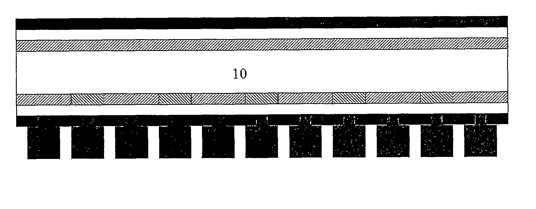
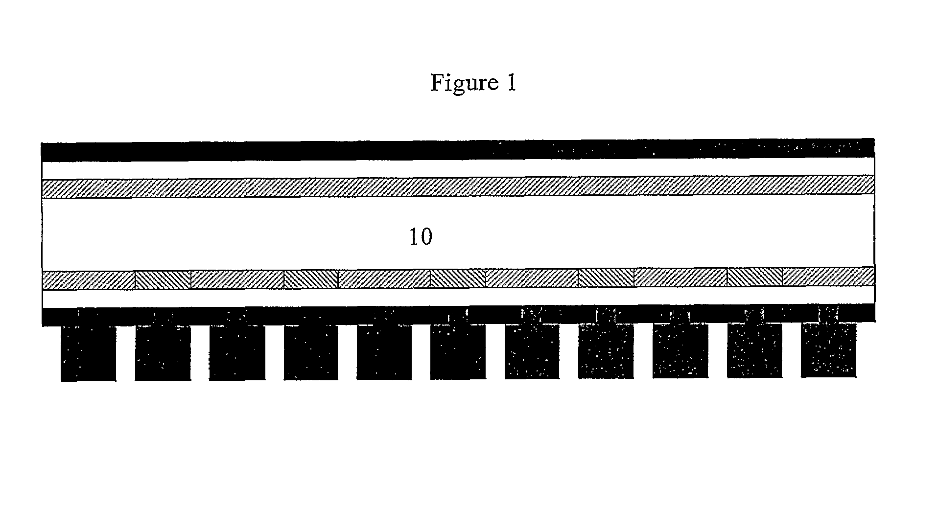
[0009]The invention relates to the choice of passivation layers and how to obtain the electrical contact with the doped regions of the wafer underlying the passivation layers. Thus the invention may employ any silicon wafer or thin film which is doped such that the wafer may be back-contacted. This includes wafers or thin films of mono-, micro-, and multi-crystalline silicon and any known and conceivable configuration of the P and N doped regions on the back side of the wafer. There may also be an optional P or N doped layer on the front side of the wafer.

[0010]The term “front side” denotes the side of the solar wafer that is exposed to the sunlight. The term “back side” is the opposite side of the front side of the wafer, and the term “back-contacted” means that all connectors are placed on the back side of the solar wafer. The term “P-doped region” means a surface area of the wafer where a doping material resulting in an increased number of positive charge carriers is added into t...


PUM


Abstract

This invention relates to a cost effective method of producing a back contacted silicon solar cell and the cell made by the method, where the method comprises applying a silicon substrate, wafer or thin film, doped on the back side with alternating P-type and N-type conductivity in an interdigitated pattern and optionally a layer of either P- or N-type on the front side of the wafer, depositing one or more surface passivation layers on both sides of the substrate, creating openings in the surface passivation layers on the back side of the substrate, depositing a metallic layer covering the entire back side and which fills the openings in the surface passivation layers, and creating openings in the deposited metallic layer such that electric insulated contacts with the doped regions on the back side of the substrate is obtained.

Description

[0001]This invention relates to a cost effective method of producing a back contacted silicon solar cell and the cell made by the method.INTRODUCTION[0002]The world supplies of fossil oil are expected to be gradually exhausted in the following decades. This means that our main energy source for the last century will have to be replaced within a few decades, both to cover the present energy consumption and the coming increase in the global energy demand.[0003]In addition, there are raised many concerns that the use of fossil energy is increasing the earth greenhouse effect to an extent that may turn dangerous. Thus the present consumption of fossil fuels should preferably be replaced by energy sources / carriers that are renewable and sustainable for our climate and environment.[0004]One such energy source is solar light, which irradiates the earth with vastly more energy than the present and any foreseeable increase in human energy consumption. However, solar cell electricity has up t...

Claims


Application Information

Patent Timeline
Patent Type & Authority Applications(United States)
IPC IPC(8): H01L31/02
CPCH01L31/02167Y02E10/547H01L31/0682H01L31/022441H01L31/02008H01L31/042H01L31/1804H01L31/186H01L31/202H01L31/208
Inventor SAUAR, ERIK
Owner RENEWABLE ENERGY CORP LTD
Why Eureka
Try Eureka