Station and method for filling a tank with a fuel gas

a technology of fuel gas and station, applied in the direction of container filling under pressure, container discharging methods, vessel construction details, etc., to achieve the effect of optimizing the level of use, limiting the number of source stores necessary, and avoiding the need to effect cascade filling cans

Active Publication Date: 2020-08-25
LAIR LIQUIDE SA POUR LETUDE & LEXPLOITATION DES PROCEDES GEORGES CLAUDE
View PDF33 Cites 4 Cited by
  • Summary
  • Abstract
  • Description
  • Claims
  • Application Information

AI Technical Summary

Benefits of technology

[0011]The use of such gas stores in the filling station offers numerous advantages.
[0012]This structure makes it possible to limit the number of source stores necessary in a filling station by optimizing their level of use. The necessity to effect cascade filling can even be eliminated.
[0013]The system enables physical separation between the hydrogen and the compression fluid by means of a flexible bladder. It also enables isobaric filling on the station side and therefore limitation of the pressure variations of the store or stores of the station. This can if necessary increase its service life.
[0014]The transfer of gas can be effected at constant pressure in the source store and the gas transferred can therefore be maintained at a constant temperature. This enables simplification of the design of a heat exchanger, if any, for cooling the gas farther downstream in the circuit.
[0031]the method includes a step of transfer of gas from the at least one source store to the tank and, simultaneously with this transfer of gas, liquid is injected into the at least one source store to limit or prevent the pressure drop in said source store,
[0032]the method includes a step of filling the at least one source store by transfer of gas from a source of pressurized fuel gas and, simultaneously with this transfer of gas, liquid is extracted in the at least one source store to limit or prevent the pressure rise in said source store,

Problems solved by technology

Moreover, this solution entails installing in the station high-capacity high-pressure stores since only a portion of the contents is actually transferred into the tank of the vehicle by such balancing (high residual quantities).
This necessitates the installation of a complex system of valves.

Method used


Image

  • Station and method for filling a tank with a fuel gas

Examples


Embodiment Construction

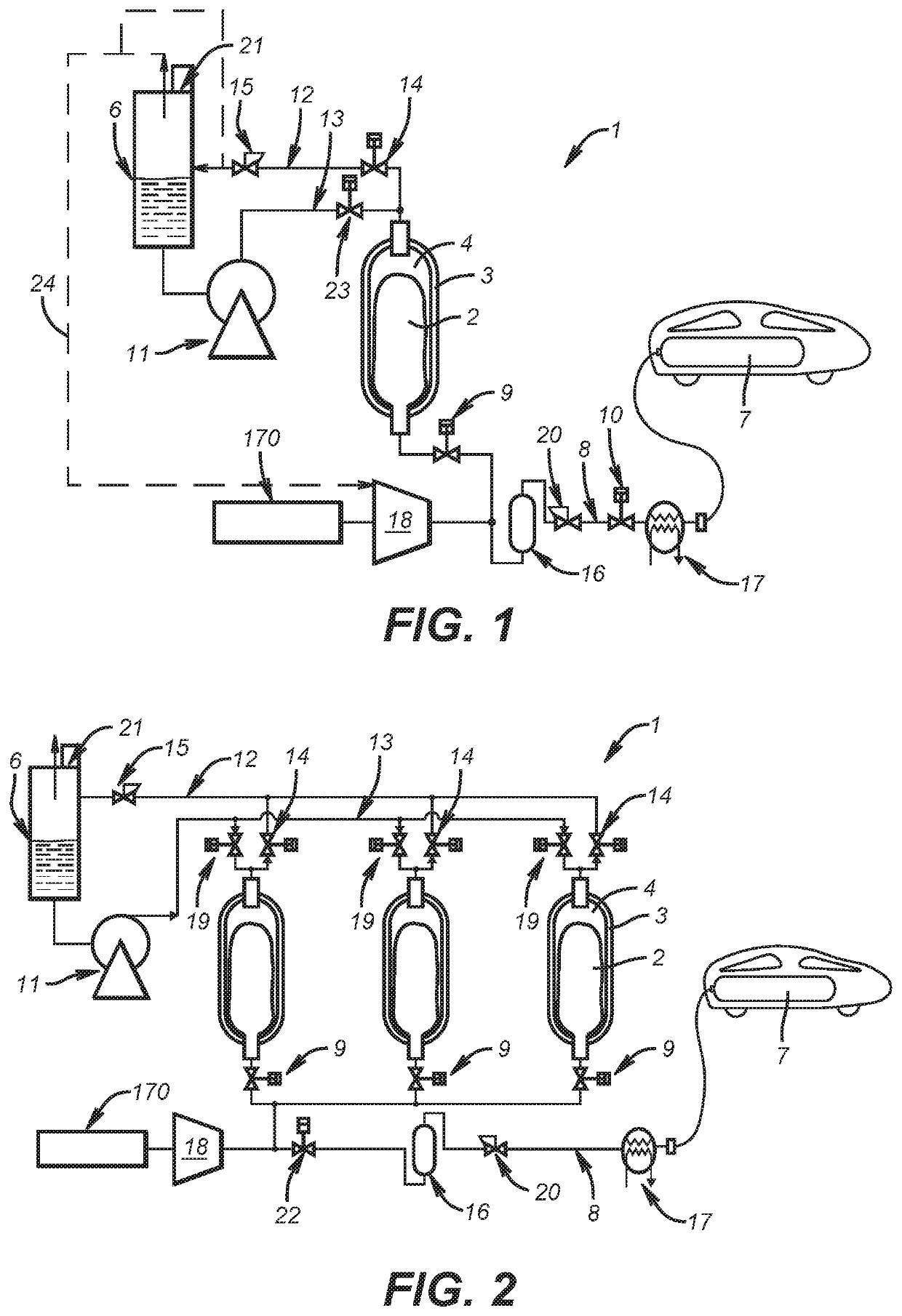
[0038]The example of a filling station 1 shown in FIG. 1 conventionally includes a source store 3 of fuel gas (such as hydrogen) and a gas transfer circuit 8. The gas transfer circuit 8 has an upstream first end connected to the source store 3 and a downstream second end intended to be in fluid communication with the tank 7 to be filled (for example via a quick-connect system at the end of a hose).

[0039]The gas transfer circuit 8 includes at least one valve 9, 10 for controlling the transfer of gas from the source store 3 to the tank 7. For example, the circuit can include between the source store 3 and the downstream end a first valve 9 (for example a controlled valve), a pressure regulator 20 then a second valve.

[0040]According to one advantageous feature, the source store 3 includes a rigid, for example composite, outer wall and a flexible sealing wall 2 that is arranged inside the space defined by the rigid outer wall.

[0041]The flexible wall 2 therefore forms a flexible bladder ...


PUM


Abstract

The invention relates to a station and method for filling a tank with a fuel gas. Said station includes at least one fuel gas source store and a gas transfer system having a first upstream end connected to the source store(s) and a second downstream end that is in fluid communication with the tank. The gas transfer system includes at least one control valve, characterized in that the at least one source store includes a rigid outer wall and a flexible sealing wall that is arranged inside the space defined by the rigid outer wall. The flexible wall defines a storage space for the fuel gas. The first upstream end of the system is connected to the storage space defined by the flexible wall. The at least one control valve is also characterized in that the space located between the flexible wall and the outer wall is connected to a system for transferring liquid into the source store in order to fill or extract the liquid in the source store and control the pressure in the store when filling and / or extracting fuel gas within the sealing wall.

Description

CROSS-REFERENCE TO RELATED APPLICATIONS[0001]This application is a § 371 of International PCT Application PCT / FR2016 / 050772, filed Apr. 5, 2016, which claims § 119(a) foreign priority to French patent application FR 1553138, filed Apr. 10, 2015.BACKGROUNDField of the Invention[0002]The present invention concerns a station and a method for filling tanks with pressurized gas.[0003]The invention more particularly concerns a station for filling a tank with a pressurized fuel gas, notably hydrogen, including at least one fuel gas source store and a gas transfer circuit having an upstream first end connected to the source store(s) and a downstream second end intended to be in fluid communication with the tank to be filled, the gas transfer circuit including at least one valve for controlling the transfer of gas from the source store to the tank.[0004]The invention applies in particular to filling pressurized hydrogen tanks.Related Art[0005]Hydrogen gas filling stations for vehicles powere...

Claims


Application Information

Patent Timeline
Patent Type & Authority Patents(United States)
IPC IPC(8): F17C5/06F17C5/00F17C13/02
CPCF17C13/025F17C5/06F17C5/007F17C2203/0619F17C2201/0185F17C2201/032F17C2227/0135F17C2205/0341Y02E60/32F17C2205/0338F17C2270/0139F17C2205/0142F17C2227/0302F17C2227/043F17C2227/0393F17C2203/0604F17C2225/036F17C2260/02F17C2223/033F17C2201/018F17C2250/0631F17C2227/0157F17C2227/0337F17C2265/065F17C2221/033F17C2225/0123F17C2227/0192F17C2223/0123F17C2205/0326F17C2221/012F17C2223/0161F17C5/00F17C11/005
Inventor ALLIDIERES, LAURENTFLYNN, JULIEDEVILLIERS, CLEMENCEFRANCOIS, THIBAUT
Owner LAIR LIQUIDE SA POUR LETUDE & LEXPLOITATION DES PROCEDES GEORGES CLAUDE
Why Eureka
Try Eureka