Electronic apparatus, display system, and method for controlling electronic apparatus

a display system and electronic technology, applied in the direction of static indicating devices, selective content distribution, instruments, etc., can solve the problem that the source apparatus to supply image data to the display device cannot be switched by operating the display devi

Active Publication Date: 2020-09-01
SEIKO EPSON CORP
View PDF11 Cites 0 Cited by
  • Summary
  • Abstract
  • Description
  • Claims
  • Application Information

AI Technical Summary

Benefits of technology

[0006]An advantage of some aspects of the invention is that an electronic apparatus connected to a display device can be operated by the display device.
[0020]This configuration can reduce the time and effort of resetting the set value that is set for image data, when registering the information of the first interface or the second interface in the table.
[0022]This configuration makes it possible to select an interface to which image data is inputted, with reference to the display screen displayed by the display device. Also, when the first interface or the second interface is selected as the interface to which image data is inputted, the switching between the interfaces provided in the electronic apparatus can be carried out via the display device.
[0026]This configuration can reduce the time and effort of resetting the set value that is set for image data inputted, when registering the information of the first interface or the second interface in the table.
[0028]This configuration makes it possible to select an interface to which image data is inputted, with reference to the display screen displayed by the display device. Also, when the first interface or the second interface is selected as the interface to which image data is inputted, the switching between the interfaces provided in the electronic apparatus can be carried out via the display device.

Problems solved by technology

However, with the display device connected to a plurality of source apparatuses via the electronic apparatus, the source apparatus to supply image data to the display device cannot be switched by operating the display device.

Method used


Image

  • Electronic apparatus, display system, and method for controlling electronic apparatus
  • Electronic apparatus, display system, and method for controlling electronic apparatus
  • Electronic apparatus, display system, and method for controlling electronic apparatus

Examples


Embodiment Construction

[0043]Hereinafter, an embodiment of the invention will be described with reference to the accompanying drawings.

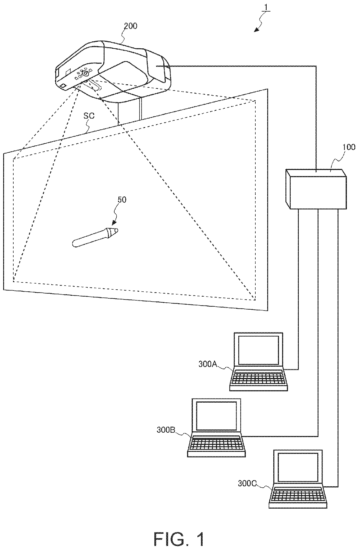
[0044]FIG. 1 shows an outline of a display system 1.

[0045]The display system 1 has a switching device 100 which operates as an electronic apparatus, a projector 200 which operates as a display device, and a plurality of image supply devices 300A to 300C. While FIG. 1 shows the display system 1 having three image supply devices 300, the number of image supply devices 300 is not limited to three. In the description below, the general term “image supply device 300” is used where the image supply devices 300A to 300C need not be particularly discriminated from each other.

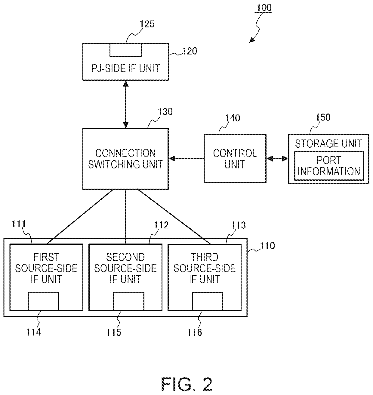
[0046]The switching device 100 is a device which switches the connection of the projector 200 with one of the image supply devices 300A to 300C to another. Specifically, the switching device 100 is a device which outputs image data supplied from a selected image supply device 300 to the projector 200. The swit...


PUM


Abstract

An electronic apparatus includes: first to third source-side IF units; and a control unit which causes one of the first to third source-side IF units to transmit image data inputted thereto, to a projector, when an operation mode of the electronic apparatus is a first operation mode, and which causes one of the first to third source-side IF units that is not the one of the first to third source-side IF units connected when in the first operation mode, to transmit image data inputted thereto, to the projector, when the operation mode of the electronic apparatus is a second operation mode. The control unit switches the operation mode to one of the first operation mode and the second operation mode in response to a change request received from the projector.

Description

CROSS-REFERENCE[0001]The entire disclosure of Japanese Patent Application No. 2017-187587, filed Sep. 28, 2017 is expressly incorporated by reference herein.BACKGROUND1. Technical Field[0002]The present invention relates to an electronic apparatus, a display system, and a method for controlling an electronic apparatus.2. Related Art[0003]According to the related art, an electronic apparatus having a plurality of input interfaces and connected to a display device is known (see, for example, JP-A-2013-235318). Source apparatuses which supply image data to the display device are connected to the plurality of input interfaces. The electronic apparatus switches the input interface to be connected to the display device in response to an operation and thus switches the source apparatus to supply image data to the display device.[0004]JP-A-2013-235318 discloses an operation panel which is connected to a projector via a dedicated cable and operates the projector. When an operation button pro...

Claims


Application Information

Patent Timeline
Patent Type & Authority Patents(United States)
IPC IPC(8): G09G3/20G03B21/10G03B21/56G06F3/03G06F3/01G06T11/60G09G3/00H04N21/422G06F3/033
CPCG03B21/56H04N21/42221G06F3/0304G06T11/60G06F3/017G03B21/10G09G3/002G06F3/011G06T2200/24G06F3/033G09G3/2096G06F3/1423
Inventor ANO, TAKAHIRO
Owner SEIKO EPSON CORP
Why Eureka
Try Eureka