Sputtering apparatus

Inactive Publication Date: 2013-10-24
CANON ANELVA CORP
View PDF3 Cites 2 Cited by
  • Summary
  • Abstract
  • Description
  • Claims
  • Application Information

AI Technical Summary

Benefits of technology

[0016]The surface state of the target can be determined according to each magnetic field pattern changed by the changing unit. Accordingly, in response to specification of the position of the magnet unit corresponding to the magnetic field pattern, the magnetic field condition which can cancel out the above magnetic field patter can be selected, Furthermore, the sputtering apparatus includes the controller which, based on the determination result by the determination unit, selects the magnetic field pattern that can be canceled out with the magnetic field pattern as an object for determination by the determination un

Problems solved by technology

However, it is difficult to directly observe whether impurity layers formed on the target, including re-deposited film of the target material and surface oxidized layer, is sufficiently removed in a state where the target is placed within the vacuum vessel.
Accordingly, a lot of time and effort are spent on the cleaning process that involves many trial-and-error elements.
The thus-reduced apparatus utilization reduces the production volume of devices, and consequently increases the manufacturing cost of the devices.
For example, the aforementioned method shown in Patent Document 2 can comparatively well remove the surface oxidized layer formed on the entire surface of the target but cannot sufficiently remove re-deposited substances of the target adhering to unspecified places.
This produces a waste of the target material and requires a certain time.
Moreover, in the case of sputtering at high voltage without using a magnet, particles ejected by sputtering disper

Method used


Image

  • Sputtering apparatus
  • Sputtering apparatus
  • Sputtering apparatus

Examples


Example

[0042]Hereinafter, a description is given of an embodiment of the present invention.

[Configuration of Sputtering Apparatus]

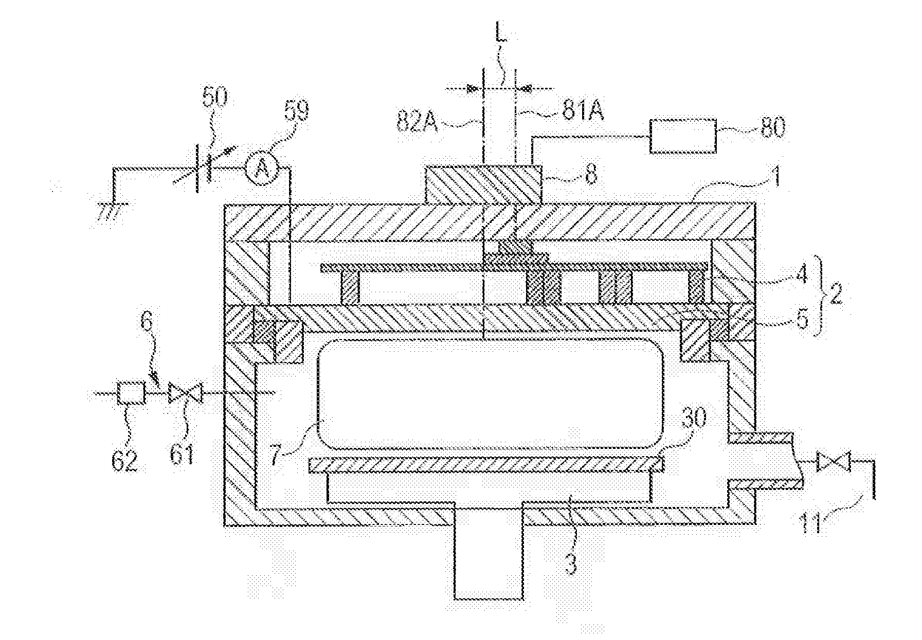
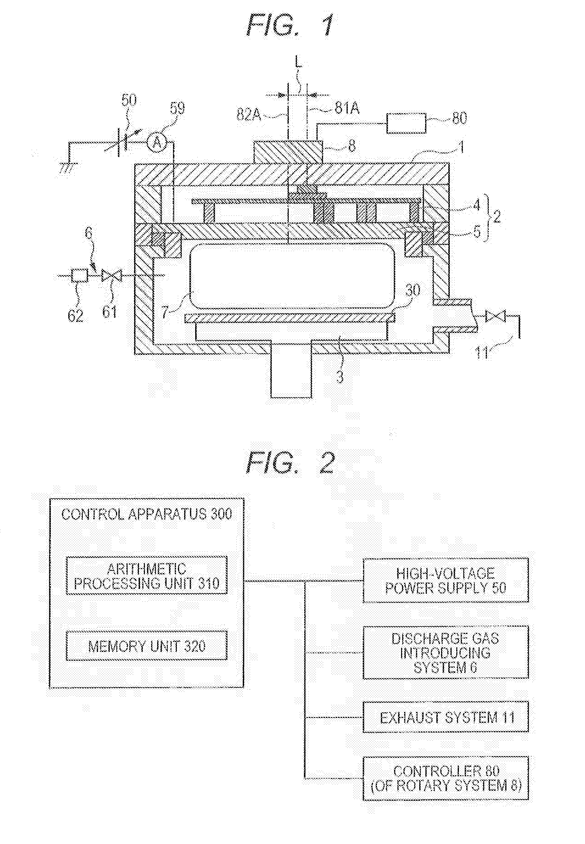
[0043]FIG. 1 is a schematic view of a sputtering apparatus according to the embodiment of the present invention. The sputtering apparatus includes: a vacuum vessel 1; an exhaust system 11 for depressurizing the vacuum vessel 1; and a target electrode 2 placed at a predetermined position within the vacuum vessel 1. The sputtering apparatus further includes: a substrate holder 3 configured to place a substrate 30 at a predetermined position facing the target electrode 2; and a discharge gas introducing system 6 introducing discharge gas within the vacuum vessel 1.

[0044]The target electrode 2 configured as described above is placed together with the substrate 30 within a vacuum processing chamber so that the surface of a target 5 thereof faces the substrate 30 as an object of thin film formation, and sputtering gas is introduced. Thereafter, electric power is suppl...


PUM

PropertyMeasurementUnit
Poweraaaaaaaaaa
Magnetic fieldaaaaaaaaaa

Abstract

The present invention provides a means capable of determining the surface state of the target to execute accurate and quick cleaning of necessary part. The means includes: a magnet unit capable of forming a magnetic field on the surface of a target; a rotary system capable of driving the magnet unit of change the magnetic field pattern; and an ammeter configured to measure target current when the magnetic field is formed by the magnet unit and discharge voltage is applied to a target electrode to which the target is attached. The position of the magnet unit is variously changed by the rotary system, and the target current is measured at each position and compared with a reference value. It is then determined whether cleaning is necessary at each position, so that cleaning can be performed only for necessary part.

Description

CROSS-REFERENCE TO RELATED APPLICATIONS[0001]This application is a continuation application of International Application No. PCT / JP2011 / 007275, filed Dec. 26, 2011, which claims the benefit of Japanese Patent Application No. 2010-292111, filed Dec. 28, 2010. The contents of the aforementioned applications are incorporated herein by reference in their entireties.TECHNICAL FIELD[0002]The present invention relates to a sputtering apparatus including a magnet unit.BACKGROUND ART[0003]Thin film formation by sputtering using a magnet, for example, magnetron sputtering, is capable of providing high-quality film and implementing high-speed film formation and therefore has been put into practical use in various fields. Manufacturing of semiconductor devices and electronic components is not exception, and the sputtering using a magnet re considered as an important technique influencing the characteristics of the devices and the like. In recent years, the semiconductor devices and electronic c...

Claims


Application Information

Patent Timeline
IPC IPC(8): C23C14/35
CPCC23C14/3407C23C14/564H01J37/3461C23C14/35H01J37/3482H01J37/3485H01J37/3476B08B7/00C23C14/3414H01J37/3405H01J37/3455
Inventor SHIBUYA, YOHSUKE
Owner CANON ANELVA CORP
Why Eureka
Try Eureka